 |
 1-Apr-2021, 12:23 AM
|
#1
|
|
Junior Member
Join Date: Mar 2021
Posts: 10
|
Trying To Make Homemade Antenna For Channel 10
http://www.tvfool.com/?option=com_wr...90385dcac211d0
All of my local channels are really UHF except for one. It is KLFY 10.1. Also, it is the weakest local channel.
I made a 4 bowtie antenna for UHF and it catches most of my local UHF channels, but not 10.1 on VHF. I made a simple dipole for 10.1, a half inch gap between the elements and a total length of 2 feet 4-13/16 inches. It catches 10.1 about 95 percent of the time.
My antenna is in a window. The antenna needs to face NW, and luckily, the closest window to the tv faces that direction. Any antenna I make will have to fit in a space that is 34" wide, 5' tall, and 4 and a half inches deep.
For better reception on just channel 10, would making more dipole type elements the same length I have give me better reception? Is there a better High VHF build? Maybe get some kind of amplifier?
I would like to have both a VHF and UHF antenna connected at the same time, but I understand that I would need some kind of combiner or diplexer, and I know nothing about that stuff.
Been reading on here a little while, and just joined. Any help would be greatly appreciated.
|

|

|
 1-Apr-2021, 2:37 AM
|
#2
|
|
Retired A/V Tech
Join Date: Aug 2012
Location: S.E. VA
Posts: 2,750
|
Quote:
Originally Posted by beebo89

|
Hello, beebo89; welcome to the forum.
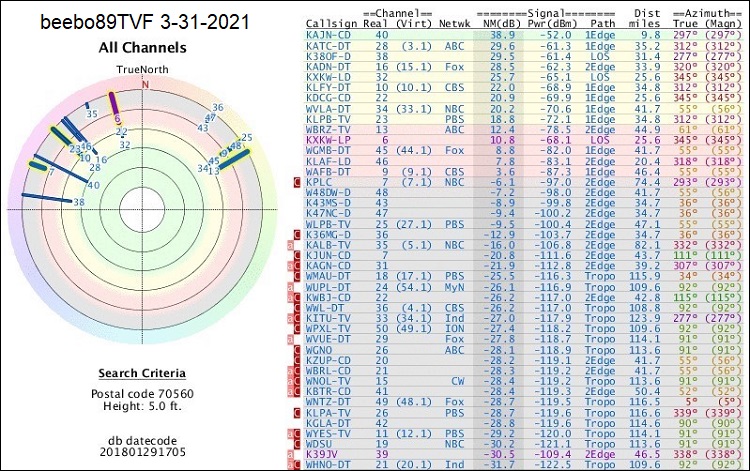
Thank you for the signal report. It appears to be an approximate report that might not be accurate for your actual location in New Iberia, LA. The location for that report is near the intersection of Center St and Spanish Towne Blvd near Lowes and Social Security Admin.
The database used to generate TVFool reports is out of date, so I did a report for that same location at rabbitears.info (the lowest antenna height it can do is 13 ft):
https://www.rabbitears.info/searchma...tudy_id=239475
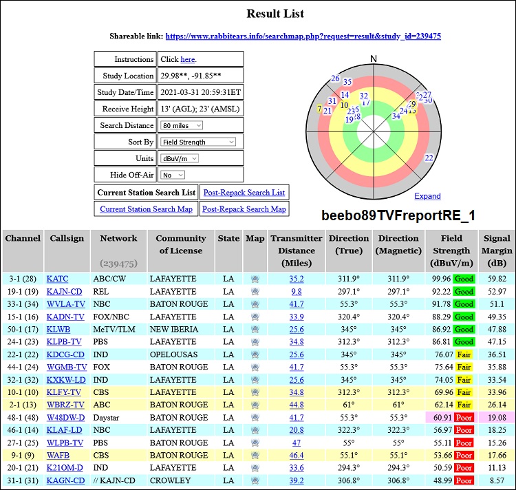
You can do your own report at this link. I use coordinates from Google maps:
https://www.rabbitears.info/searchmap.php
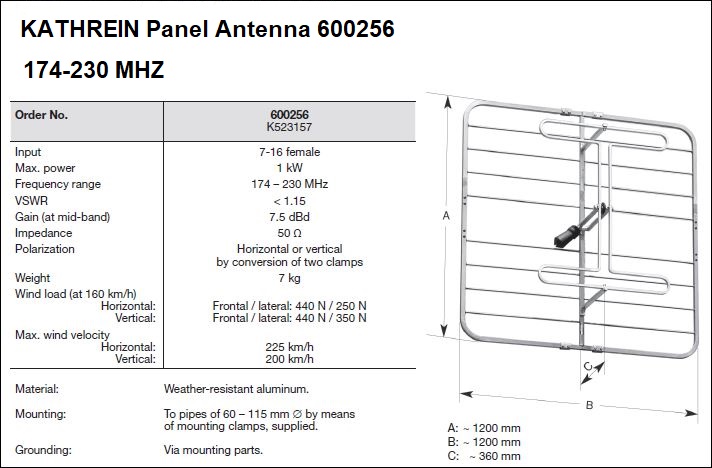
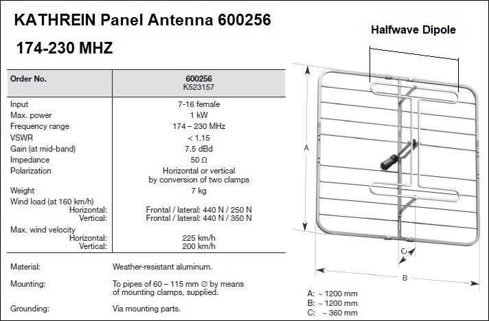
If a simple dipole doesn't have enough gain, you could stack two folded dipoles and add a reflector. This is a commercial broadcast version of the concept:
Quote:
|
I would like to have both a VHF and UHF antenna connected at the same time, but I understand that I would need some kind of combiner or diplexer, and I know nothing about that stuff.
|
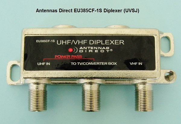
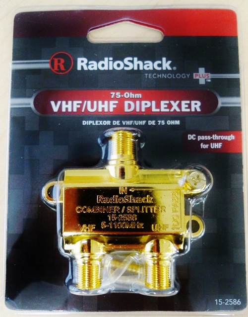
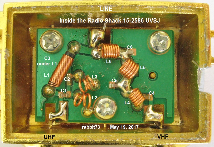
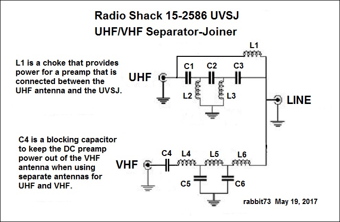
The correct device to combine a UHF antenna with a VHF antenna is a UVSJ (UHF/VHF Separator/Joiner) which is indeed a diplexer.
https://store.antennasdirect.com/UHF...Combiners.html
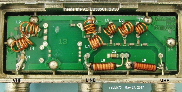
This is also available, but I haven't tested it:
https://www.amazon.com/Weatherproof-.../dp/B0744NTJX8
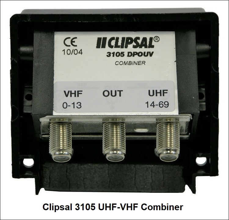
You can also try eBay for the Radio Shack 15-2586.
Last edited by rabbit73; 1-Apr-2021 at 3:27 AM.
|

|

|
 1-Apr-2021, 5:19 PM
|
#3
|
|
Junior Member
Join Date: Mar 2021
Posts: 10
|
Thanks for the reply. The rabbitearsinfo graph is much more accurate, thanks.
The info I have found seems to indicate that a folded dipole like you mentioned works better than what I made, but I am having trouble finding small aluminum tubing. If I would go that route, is the length of a folded dipole the same as a simple dipole? What is the distance between the top part of the element and the bottom part? What is the gap where the balun ties in? This would all be for channel 10, which if I understand correctly is 195 MHz.
The reception I am getting now is just under where it needs to be, I am wondering if my problems would be solved with a preamp? The limited info I have found so far is that a really powerful preamp can be too strong if you are fairly close to the stations. I am guessing I need a low to mid level preamp? Can you, or anyone else, please recommend one?
|

|

|
 1-Apr-2021, 7:28 PM
|
#4
|
|
Retired A/V Tech
Join Date: Aug 2012
Location: S.E. VA
Posts: 2,750
|
Quote:
Originally Posted by beebo89

The info I have found seems to indicate that a folded dipole like you mentioned works better than what I made, but I am having trouble finding small aluminum tubing.
|
You could try small diameter copper tubing, or bare 8 gauge solid copper ground wire from Lowes or Home Depot.
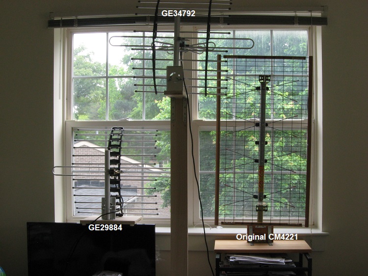
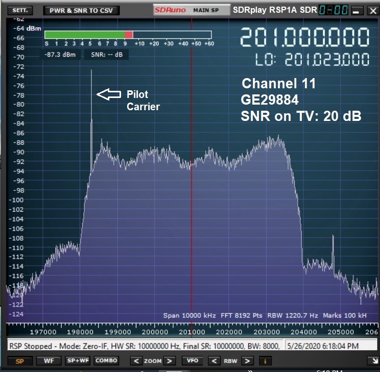
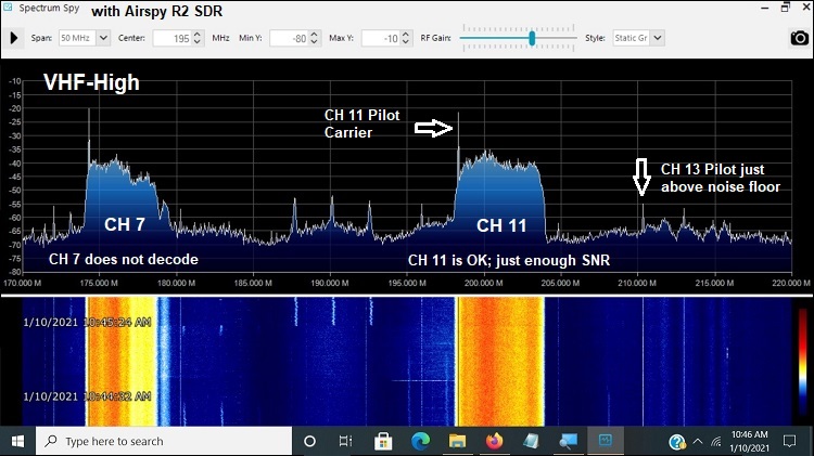
I have a GE 29884 antenna in my window that has a VHF aluminum folded dipole, but that might not have quite enough gain for your location. The folded dipole is about 29" long. I use it for Channel 11:
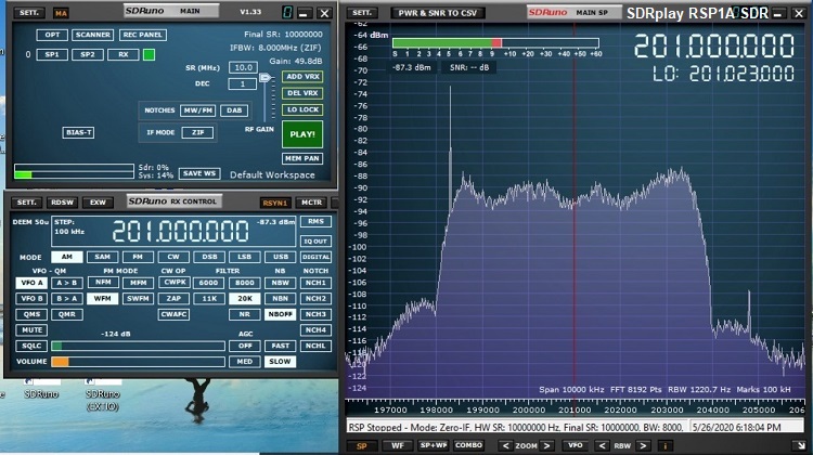
The signal looks pretty good on my SDR, in spite of the high noise level on VHF at my location:
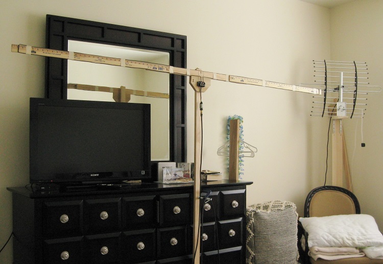
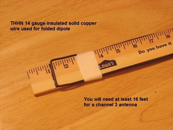
I made a folded dipole for channel 3 using yardsticks and THHN 14 gauge insulated solid copper wire.
Quote:
|
If I would go that route, is the length of a folded dipole the same as a simple dipole?
|
Yes. I use this formula:
5540/freq in MHz
Channel 10 is 192 to 198 MHz, center freq is 195 MHz
5540/195 = 28.4 inches
Quote:
|
What is the distance between the top part of the element and the bottom part? What is the gap where the balun ties in? This would all be for channel 10, which if I understand correctly is 195 MHz.
|
Just go by the diagram as a starting point for experimentation. If you want precise answers, the antenna would have to be modeled by computer modeling, which I don't do because it is too tedious. I would rather do antenna performance measurements using TV SNR, my signal level meter, and SDR images.
Quote:
|
The reception I am getting now is just under where it needs to be, I am wondering if my problems would be solved with a preamp? The limited info I have found so far is that a really powerful preamp can be too strong if you are fairly close to the stations. I am guessing I need a low to mid level preamp? Can you, or anyone else, please recommend one?
|
The Channel Master Titan 2 Medium Gain Preamplifier (Version 3) CM7778V3 might be suitable.
https://www.channelmaster.com/collec...on-3-cm-7778v3
A less expensive alternative is the CM3410 distribution amp (15 dB).
I use the more expensive CM7777HD Amplify, which has low and high gain settings, for my test setups.
It is possible to just amplify the weaker Channel 10 signal before the UVSJ. Connect the output of the power inserter to the VHF input of the UVSJ.
Last edited by rabbit73; 2-Apr-2021 at 12:00 AM.
|

|

|
 2-Apr-2021, 3:26 AM
|
#5
|
|
Junior Member
Join Date: Mar 2021
Posts: 10
|
Wow, that is a load of great info, thanks a million!!
I think I will make some folded dipoles out of that solid 8 gauge you mentioned, and then if needed I will get an amplifier. Thanks again.
|

|

|
 4-Apr-2021, 1:27 AM
|
#6
|
|
Junior Member
Join Date: Mar 2021
Posts: 10
|
What material makes a good insulator? My guess is that wood is not very good.
|

|

|
 4-Apr-2021, 1:56 AM
|
#7
|
|
Retired A/V Tech
Join Date: Aug 2012
Location: S.E. VA
Posts: 2,750
|
Quote:
Originally Posted by beebo89

What material makes a good insulator? My guess is that wood is not very good.
|
Yeah, wood isn't too bad until it gets damp.
Many materials are available:
PVC pipe
PVC rectangular building materials from Best Buy and Lowes
Clear sheet Plexiglass (acrylic); cracks easily
Clear sheet Lexan (polycarbonate) 1/4" thick; my favorite
Black sheet Delrin (acetal); best insulator, but expensive
Last edited by rabbit73; 4-Apr-2021 at 2:01 AM.
|

|

|
 4-Apr-2021, 11:32 PM
|
#8
|
|
Senior Member
Join Date: Dec 2009
Location: Delmar, NY
Posts: 1,236
|
Quote:
Originally Posted by beebo89

What material makes a good insulator? My guess is that wood is not very good.
|
Here’s my trick. Take what material you have and put it in the microwave with a cup of water for one minute. If the plastic got warm, it has poor RF characteristics.
My favorite for strength and dielectric ability is fiberglass.
|

|

|
 6-Apr-2021, 5:55 PM
|
#9
|
|
Junior Member
Join Date: Mar 2021
Posts: 10
|
I am now making an antenna to put in the window which will be made of four folded dipole elements. Being that it is in the window I will have to stack them on top of each other. Is there a certain amount of space to have between the different elements? The window is five feet tall and wide enough for the elements to fit. All the elements are 2' 4-13/16'' for real channel 10, the only channel I have trouble catching.
How do I wire it? The only wiring I have ever seen was for a UHF antenna that had 4 bowties. The balun tied in at the middle, and the wiring started from the top bowtie, crossed over to get to the 2nd bowtie, then went straight down to the 3rd bowtie, then crossed over to get to the last bowtie. Assuming that was correct for UHF, would that be the same for four VHF elements?
|

|

|
 6-Apr-2021, 7:32 PM
|
#10
|
|
Junior Member
Join Date: Mar 2021
Posts: 10
|
I plan on using stranded copper wire to connect the elements. Is that ok to use? Any particular gauge is recommended?
|

|

|
 6-Apr-2021, 11:13 PM
|
#11
|
|
Retired A/V Tech
Join Date: Aug 2012
Location: S.E. VA
Posts: 2,750
|
Quote:
Originally Posted by beebo89

I am now making an antenna to put in the window which will be made of four folded dipole elements. Being that it is in the window I will have to stack them on top of each other. Is there a certain amount of space to have between the different elements? The window is five feet tall and wide enough for the elements to fit. All the elements are 2' 4-13/16'' for real channel 10, the only channel I have trouble catching.
How do I wire it? The only wiring I have ever seen was for a UHF antenna that had 4 bowties. The balun tied in at the middle, and the wiring started from the top bowtie, crossed over to get to the 2nd bowtie, then went straight down to the 3rd bowtie, then crossed over to get to the last bowtie. Assuming that was correct for UHF, would that be the same for four VHF elements?
|
You have departed considerably from the example I posted. The example is two stacked halfwave folded dipoles.
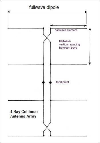
A bowtie antenna uses fullwave dipoles:
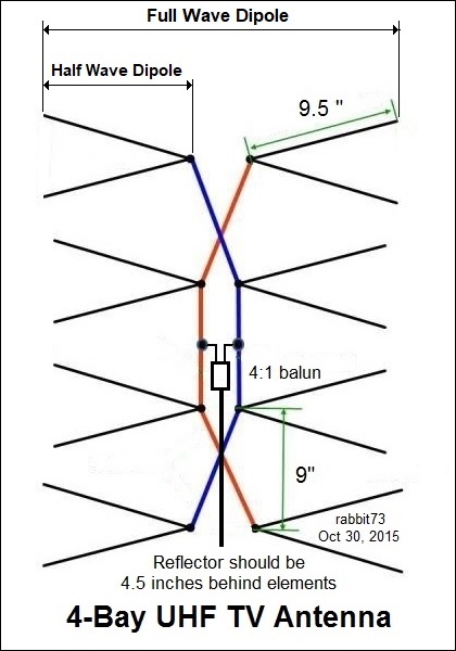
If you want to use the bowtie design, it would need to be TWICE as wide.
The bowtie antenna is derived from the collinear array, The bowties instead of the straight elements gives greater bandwidth.
Last edited by rabbit73; 6-Apr-2021 at 11:48 PM.
|

|

|
 6-Apr-2021, 11:30 PM
|
#12
|
|
Junior Member
Join Date: Mar 2021
Posts: 10
|
I'm sorry, I didn't explain my self well. I was using the 4 bowtie UHF as an example of wiring an antenna. All the searching I have done, the only example of how to wire the elements together were for a UHF antenna like that one.
Although all but one of of my local channels are UHF, I have no trouble catching them all with a simple dipole (except one UHF channel that I am not really worried about). The only channel I have trouble with is 10, which is real 10.
I may be way off because this is all new to me, but If one folded dipole is good, four must better. So I am making four of them, all for channel 10. Do I criss cross the wiring like lacing a shoe, do like the UHF antenna I mentioned, or some other setup?
|

|

|
 6-Apr-2021, 11:33 PM
|
#13
|
|
Junior Member
Join Date: Mar 2021
Posts: 10
|
In diagrams, I see 4:1 baluns and 1:1 baluns. Which one do I need? What are the ones that are sold in most stores, the 75-300 ohms type?
|

|

|
 7-Apr-2021, 12:04 AM
|
#14
|
|
Retired A/V Tech
Join Date: Aug 2012
Location: S.E. VA
Posts: 2,750
|
Quote:
Originally Posted by beebo89

I'm sorry, I didn't explain my self well. I was using the 4 bowtie UHF as an example of wiring an antenna. All the searching I have done, the only example of how to wire the elements together were for a UHF antenna like that one.
Although all but one of of my local channels are UHF, I have no trouble catching them all with a simple dipole (except one UHF channel that I am not really worried about). The only channel I have trouble with is 10, which is real 10.
I may be way off because this is all new to me, but If one folded dipole is good, four must better. So I am making four of them, all for channel 10. Do I criss cross the wiring like lacing a shoe, do like the UHF antenna I mentioned, or some other setup?
|
I guess I didn't make it very clear. You can not wire your 4 halfwave dipoles together like the fullwave dipoles in a UHF bowtie antenna and expect it to work properly.
Two stacked halfwave folded dipoles with a reflector will give you about the same gain as 4 stacked halfwave dipoles without a reflector; about 6 dB.
You asked my advice and I have given it.
It's your antenna, so you are free to wire it any way you want to wire it.
It doesn't matter to me.
Out of curiosity, I might try to build one like the example for my Channel 11 to prove or disprove the theory. 
|

|

|
 7-Apr-2021, 12:26 AM
|
#15
|
|
Junior Member
Join Date: Mar 2021
Posts: 10
|
Oh, I get it. I saw the 2 stacked folded dipole you posted. I did not realize that that was the optimal way to go with folded dipoles, similar to a small antenna is good, a bigger antenna is better. Making it with 2 instead of 4 will be easier and quicker. Thanks for all the help, it is greatly appreciated.
|

|

|
 7-Apr-2021, 1:36 AM
|
#16
|
|
Retired A/V Tech
Join Date: Aug 2012
Location: S.E. VA
Posts: 2,750
|
Quote:
Originally Posted by beebo89

Oh, I get it. I saw the 2 stacked folded dipole you posted. I did not realize that that was the optimal way to go with folded dipoles, similar to a small antenna is good, a bigger antenna is better. Making it with 2 instead of 4 will be easier and quicker. Thanks for all the help, it is greatly appreciated.
|
In theory, it is possible to make a coax phasing harness for 4 stacked ordinary dipoles, but it is quite involved. Different types of coax are used and they must be cut to specific lengths according to frequency to make 1/4 wave matching transformers.
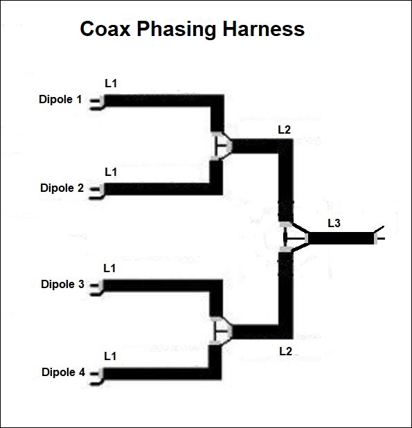
It is also possible to construct a power divider. Here is one for 2 antennas; one can also be made for 4 antennas.
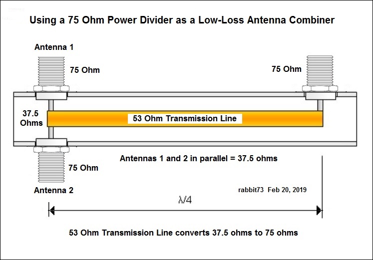 https://www.qsl.net/dk7zb/Stacking/splitter.htm
I tried to pick an easier way for you.
Last edited by rabbit73; 7-Apr-2021 at 6:58 PM.
|

|

|
 7-Apr-2021, 3:23 AM
|
#17
|
|
Retired A/V Tech
Join Date: Aug 2012
Location: S.E. VA
Posts: 2,750
|
Quote:
Originally Posted by beebo89

The only channel I have trouble with is 10, which is real 10.
I may be way off because this is all new to me, but If one folded dipole is good, four must better. So I am making four of them, all for channel 10. Do I criss cross the wiring like lacing a shoe, do like the UHF antenna I mentioned, or some other setup?
|
If you want to experiment with 300 ohm twinlead, try this:
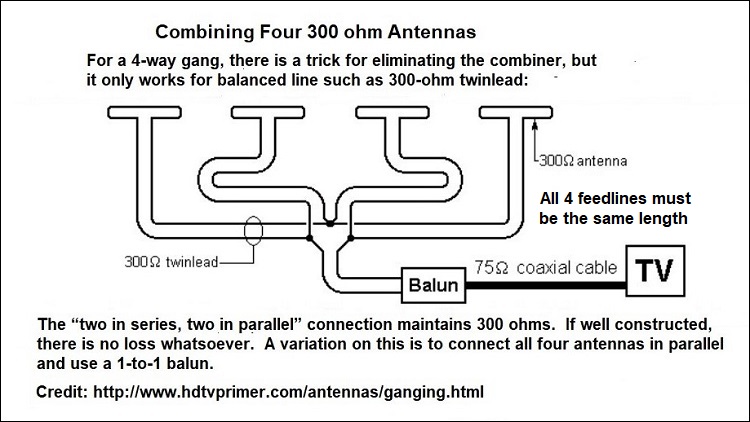 http://www.hdtvprimer.com/antennas/ganging.html
300 ohm twinlead is getting hard to find now
https://mfjenterprises.com/products/mfj-18t050
Last edited by rabbit73; 7-Apr-2021 at 11:10 PM.
|

|

|
 8-Apr-2021, 11:23 PM
|
#18
|
|
Junior Member
Join Date: Mar 2021
Posts: 10
|
Can I use the amplifier from this antenna?
I finally made the twin folded dipole antenna. It works well but I will indeed need an amplifier. I have a Winegard amplified antenna similar to this one. Would it be possible to remove the antenna and use the amplifier with the antenna I made? If not I will get one of the ones suggested earlier.
https://www.amazon.com/ANTAN-Amplifi...NsaWNrPXRydWU=
|

|

|
 9-Apr-2021, 2:41 AM
|
#19
|
|
Retired A/V Tech
Join Date: Aug 2012
Location: S.E. VA
Posts: 2,750
|
Quote:
Originally Posted by beebo89

I finally made the twin folded dipole antenna. It works well but I will indeed need an amplifier. I have a Winegard amplified antenna similar to this one. Would it be possible to remove the antenna and use the amplifier with the antenna I made? If not I will get one of the ones suggested earlier.
https://www.amazon.com/ANTAN-Amplifi...NsaWNrPXRydWU= |
You might be able to do that, but you would have to cut the cable off the flat antenna and connect it to the center of the phasing line between the two dipoles. If that doesn't work, try connecting the cable to a balun, and then connect the two wires of the balun to the center of the phasing line between the two folded dipoles.
|

|

|
 Posting Rules
|
You may not post new threads
You may not post replies
You may not post attachments
You may not edit your posts
HTML code is Off
|
|
|
|
|

