 |
 10-Dec-2009, 8:04 PM
|
#1
|
|
Janitor
Join Date: Dec 2009
Posts: 54
|
Quick Reference For Some Selected Antennas
This thread will hold information gathered for specific antennas.
A few notes about the information provided: - All gain figures have been adjusted to dBd (gain relative to a dipole antenna). This helps us make sure everything is being compared on an even scale. If you have an antenna that specifies its gain in dBi (gain relative to an isotropic antenna), then you'll need to subtract 2.15 dB from that number to get the equivalent value in dBd.
- The Noise Margin numbers generated by the signal analysis tools are relative to a 0 dBd antenna. This means any antenna with a positive dBd value will help you gain NM (increase your net NM) and any antenna with a negative dBd value will cause you to lose NM (decrease your net NM). The reason we use dBd here is because of this convenient relationship to Noise Margin calculations.
- Antennas are strongly affected by nearby objects, especially if they contain conductive materials. If you install an antenna too close to other objects, it can have a big impact on its antenna pattern and performance.
- There is usually no one best antenna for any given situation. In addition to performance specifications, it is also important to consider factors such as aesthetics, mounting location, mounting difficulty, additional stress caused by snow/wind/ice, aiming sensitivity, resistance to multi-path, etc. Gain is good, but it is only one consideration among many when choosing an antenna.
- All antenna patterns shown here have their main lobe (the part you want aimed at the transmitters) pointing to the right. The purpose of the antenna patterns is to provide a rough idea of what the "sweet spot" of the antenna looks like. In some scenarios it may be important to know how "squashed" the antenna pattern is in both the horizontal and vertical directions.
- We'll try our best to provide accurate information here, but keep in mind that mistakes are always possible, and that most antenna specifications are just approximations. Variations in manufacturing consistency, damage to the antenna, effects from nearby objects, and other uncontrolled variables can cause the antenna performance to change. If you think there are errors, please let us know, and these posts will be updated as needed.
Jump to specific antennas:
Last edited by andy.s.lee; 17-Dec-2009 at 2:33 AM.
|

|
|
|
10-Dec-2009, 8:04 PM
|
#2
|
|
Janitor
Join Date: Dec 2009
Posts: 54
|
Rabbit Ears and Loop
Typical Application
- Indoors, set-top, suitable for strong local signals with minimal multi-path.
Size
- Rabbit ears can be up to about 80" across if fully extended horizontally. If set up in a "V" configuration, they can reach up to about 40" high.
- Loops are typically about 8" across, but if they are enclosed in plastic, it may appear to be bigger.
Operating Frequencies
- Rabbit ears (when extended) are good at handling VHF
- Loops are good at handling UHF
Gain
- Rabbit ears typically get close to 0 dBd if they are extended to the proper length (almost an ideal dipole). If set up in a "V" configuration, the gain is a little less, but then doesn't require as much horizontal space in your living room. The peak of the gain curve can be optimized for different channels by changing the length of the elements. Longer antenna elements (fully extended) favor lower channel numbers and shorter elements (about half extended) favor higher ones.
Rabbit Ears (this graph is for elements extended about 40", the gain peak can be moved to higher channels by shortening the elements)
 - Loops typically get between -2 and +2 dBd at different points within the UHF band. If the antenna has a user-selectable tuning circuit (typically a multi-position switch on the base), it may be possible to move the peak of the gain curve to higher or lower frequencies, depending on which channel you want to watch.
Loop
 Aiming
- Rabbit ears are optimally aimed by making the broad side of the antenna face the transmitter. That is, if you imagine the signal coming from the transmitter, you want it to come in perpendicular to the rabbit ear elements. The gain is roughly the same from the "front" or the "back", so either side will work.
Rabbit Ears in horizontal configuration
 Rabbit Ears in "V" configuration
 - Loops should be aimed so that the face of the loop is pointed at the transmitter. That is, the axis going through the center of the loop should aligned with the transmitter's direction. The gain is roughly the same from the "front" or the "back", so either side will work.
Loop

Last edited by andy.s.lee; 14-Dec-2009 at 7:45 PM.
|
|
|
|
|
10-Dec-2009, 8:10 PM
|
#3
|
|
Janitor
Join Date: Dec 2009
Posts: 54
|
Silver Sensor
Description
This small log periodic antenna was first introduced by a U.K. based company called Antiference. It was later licensed for sale in the U.S. by Zenith, and now it is being licensed by Philips. The influence of this popular antenna design can also be seen in copy-cat products like the Terk HDTVi (which adds rabbit ears to mix).
Typical Application
- Indoors, set-top, suitable for strong to medium signals with only mild multi-path.
Size
- Approximately 13.5" wide, 13" long, and 9.5" tall
Operating Frequencies
- UHF only
- Copy-cat products that include rabbit ears may also provide some VHF capability. See the post on rabbit ears to get a feel for the potential VHF performance.
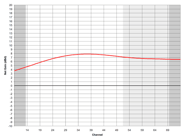
Gain
- This antenna gets between 3 and 6 dBd at different points within the UHF band.

Aiming
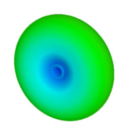
- This antenna has its maximum gain out its front (the "nose of the airplane"). The tip of the antenna should be aimed toward the transmitters. The horizontal beam width is approximately +/-30 degrees from side to side, in case you need to fetch channels spread apart by several degrees.
- Even though this antenna allows you to mount the elements in a vertical orientation, this is usually sub-optimal for TV reception. TV signals are horizontally polarized, so this antenna will usually perform better in it normal horizontal configuration.

Last edited by andy.s.lee; 14-Dec-2009 at 6:37 AM.
|
|
|
|
|
10-Dec-2009, 8:15 PM
|
#4
|
|
Janitor
Join Date: Dec 2009
Posts: 54
|
2 Bay Bowtie
Description
Several manufacturers make 2 bay bowtie antennas because of its simple design, reasonable gain, and compact size. Some of the more common variants include the Channel Master 4220 and Antennas Direct DB2.
Typical Application
- Outdoors, patio or roof-top, suitable for strong to medium signals with only mild multi-path.
- Although these are intended for outdoor use, they are also small enough to be considered for indoor use as long as you can figure out a way to mount it and don't mind the size/aesthetics/weight (it's a bit bulkier than your standard set-top antenna).
Size
- Approximately 20" wide, 18" tall, and 7" thick
Operating Frequencies
- UHF only
Gain
- This antenna gets between 4 and 8 dBd at different points within the UHF band.
Aiming
- This antenna has its maximum gain out its front. The face with the bowties should be aimed toward the transmitters. The horizontal beam width is approximately +/-30 degrees from side to side (60 degrees total width), in case you need to fetch channels spread apart by several degrees.

Last edited by andy.s.lee; 11-Feb-2010 at 5:59 PM.
|
|
|
|
|
10-Dec-2009, 8:15 PM
|
#5
|
|
Janitor
Join Date: Dec 2009
Posts: 54
|
4 Bay Bowtie
Description
Several manufacturers make 4 bay bowtie antennas because of its simple design and good gain. Some of the more common variants include the Channel Master 4221, Antennas Direct DB4, and Winegard 4400. This design is also the basis of a very popular DIY "coat hanger" antenna seen on the internet.
Typical Application
- Outdoors, roof-top, suitable for medium to weak signals with moderate multi-path.
Size
- Approximately 20" wide, 35" tall, and 7" thick
Operating Frequencies
- UHF only
Gain
- This antenna gets between 6 and 13 dBd at different points within the UHF band.

Aiming
- This antenna has its maximum gain out its front. The face with the bowties should be aimed toward the transmitters. The horizontal beam width is approximately +/-30 degrees from side to side (60 degrees total width), in case you need to fetch channels spread apart by several degrees.
- This antenna pattern is very similar to the pattern of a 2 bay bowtie antenna except that the main lobe has been "squashed" in the vertical direction. The horizontal beam width remains about the same, but the vertical beam width is smaller.

Last edited by andy.s.lee; 11-Feb-2010 at 6:05 PM.
|
|
|
|
 Posting Rules
|
You may not post new threads
You may not post replies
You may not post attachments
You may not edit your posts
HTML code is Off
|
|
|
|
|


