 |
|
 7-Aug-2019, 2:43 PM
|
#1
|
|
Member
Join Date: Nov 2010
Posts: 54
|
ANT751 VHF Conversion?
Is it possible to convert this antenna from UHF/VHF to VHF? I have the Y5-7-13 VHF antenna (discontinued) and the ANT751 and after comparing and studying them side by side, I noticed the ANT751 only has 3 elements that are connected to the transformer/balun whereas the Y5 the complete antenna is connected to the balun. Would taking a piece of aluminum wire and connecting the two leads to the square pipe like the Y5 make the complete antenna similar to the Y5. Would this increase the VHF gain? I'm in experimentation mode lol
|

|

|
 7-Aug-2019, 3:24 PM
|
#2
|
|
Member
Join Date: Nov 2010
Posts: 54
|
My reason and thinking on this is that if this is possible and works, the 751 would make a great companion VHF antenna to the DB4e and HDB4X with a smaller footprint.
|

|

|
 7-Aug-2019, 3:47 PM
|
#3
|
|
Moderator
Join Date: Oct 2010
Location: Greater Seattle Area
Posts: 4,773
|
To be sure I was remembering correctly, I went out to my shop and took a look at my Y5-7-13 that's been sitting in storage for the last few years. On mine, only the folded dipole section is directly connected to the matching transformer balun. My Y10-7-13 on the other-hand has two folded dipole sections coupled by a phasing/matching line.
The YX-7-13 models offer increased gain in the H-VHF band because all of the elements are sized and spaced so as to be tuned for that band. The ANT-751 on the other-hand has fewer elements sized and spaced for the H-VHF band and the remaining shorter elements are providing the UHF capability. The phasing/impedance matching lines are tuned so as to combine signal from both sections (UHF & VHF) and deliver it to the feed point at the correct impedance.
It may not be intuitive, but the remaining elements with no direct connection to the phasing lines are connected to each other through inductance and some small amount of capacitance. If you change one element or a phasing line you'll be changing the tuning and response pattern of the entire antenna.
Experiment away, but unless you have the equipment to accurately test the effects of you changes, you'll most likely find any changes to the antenna will be negative, some subtle and some not so subtle.
I would expect the Y5-7-13 to have at least 2 or 3 dB more gain in the H-VHF band compared to an ANT-751. If you combine them with a UVSJ you'll have the UHF performance of the ANT-751 and the H-VHF performance of the Y5-7-13.
I share you enthusiasm for experimenting. There are several yagi antenna calculators to be found searching the interwebs... I've built a few UHF and VHF antennas and had fun along with success in most cases.
__________________
If the well is dry and you don't see rain on the horizon, you'll need to dig the hole deeper. (If the antenna can't get the job done, an amp won't fix it.)
(Please direct account activation inquiries to 'admin')
|

|

|
 7-Aug-2019, 3:49 PM
|
#4
|
|
Moderator
Join Date: Oct 2010
Location: Greater Seattle Area
Posts: 4,773
|
Quote:
Originally Posted by freetvplease

My reason and thinking on this is that if this is possible and works, the 751 would make a great companion VHF antenna to the DB4e and HDB4X with a smaller footprint.
|
I'd suggest using a UVSJ with the unmodified ANT-751 connected to the VHF port and the UHF antenna attached to the UHF port.
__________________
If the well is dry and you don't see rain on the horizon, you'll need to dig the hole deeper. (If the antenna can't get the job done, an amp won't fix it.)
(Please direct account activation inquiries to 'admin')
|

|

|
 7-Aug-2019, 3:54 PM
|
#5
|
|
Retired A/V Tech
Join Date: Aug 2012
Location: S.E. VA
Posts: 2,750
|


Quote:
Originally Posted by freetvplease

Would this increase the VHF gain? I'm in experimentation mode lol
|
No, it would decrease the VHF gain.
Even without the modification, the 751 has less VHF gain than the Y5-7-13.
To satisfy your own curiosity, try it.
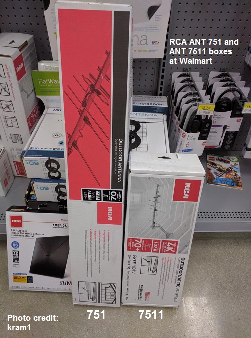
Sometimes the 7511 (in short box) is sold as the 751 (in long box), but it isn't as good:


Last edited by rabbit73; 7-Aug-2019 at 4:26 PM.
|

|

|
 7-Aug-2019, 3:55 PM
|
#6
|
|
Moderator
Join Date: Oct 2010
Location: Greater Seattle Area
Posts: 4,773
|
Antenna design is sorta like golf... If you hit the ball just right, it goes in the cup... Left, right, long or short are all a miss. De-tuning an antenna in resonance or impedance either high or low will cause a 'miss'.
__________________
If the well is dry and you don't see rain on the horizon, you'll need to dig the hole deeper. (If the antenna can't get the job done, an amp won't fix it.)
(Please direct account activation inquiries to 'admin')
|

|

|
 7-Aug-2019, 4:21 PM
|
#7
|
|
Member
Join Date: Feb 2019
Posts: 35
|
A bit off topic but out of curiosity I had picked up an ANT751r (longer box) having read here that its VHF would be better than the ANT751e (shorter box but blue) i tried.
It could have been the weather or stations (repack?) but the ANT751r did not pull in VHF 13 or UHF 44 as well as the ANT751e for me. I mean vhf 13 could not be pulled in for nothing with the ANT751r.... Looking at rabbit ears repack it looks like 13 may have move to 12.. uhf 44 to 27.. but my TV always put uhf 44 on 5 and 5 would not come in with the ANT751r...
The ANT751e worked for my stations and location but the higher VHF and UHF were the most weak. I was really impressed with the antenna...but definitely need a bigger one in my wooded location.
Last edited by RMinNJ; 7-Aug-2019 at 4:23 PM.
|

|

|
 7-Aug-2019, 4:32 PM
|
#8
|
|
Retired A/V Tech
Join Date: Aug 2012
Location: S.E. VA
Posts: 2,750
|
The 751e is the latest design; more like the original 751.
It's very confusing when they use the same basic model number for different antennas.
Channel Master did the same thing with the 7777 preamp; very confusing.
|

|

|
 7-Aug-2019, 4:36 PM
|
#9
|
|
Member
Join Date: Nov 2010
Posts: 54
|
On both my Y10 and Y5 antennas the connection with the balun is actually connected to the whole antenna because all the elements are connected through the square tubing as a whole. Does this make sense? I'm kinda thinking that If I replicated this with the 751 it may replicate the performance of the Y5 to a degree and being smaller. I understand this antenna is different from a VHF one but I'm curious if it's properties will lend itself to the VHF side.
I'll get back as soon as I can try this. Thanks
|

|

|
 7-Aug-2019, 4:46 PM
|
#10
|
|
Member
Join Date: Nov 2010
Posts: 54
|
rabbit73 from the picture you posted I can see that the 7511 is missing an element that the 751 has
|

|

|
 7-Aug-2019, 5:07 PM
|
#11
|
|
Member
Join Date: Nov 2010
Posts: 54
|
OK, so I used a piece of copper to connect the 3 elements to the whole antenna. No difference with the VHF side but did slightly degrade a couple UFH channels but nothing to complain about. Oh well
|

|

|
 7-Aug-2019, 5:56 PM
|
#12
|
|
Member
Join Date: Nov 2010
Posts: 54
|
My next experiment is to combine the 751 with the HDB4X and see if the VHF gain from both helps each other.
|

|

|
 7-Aug-2019, 6:36 PM
|
#13
|
|
Moderator
Join Date: Oct 2010
Location: Greater Seattle Area
Posts: 4,773
|
Quote:
Originally Posted by freetvplease

On both my Y10 and Y5 antennas the connection with the balun is actually connected to the whole antenna because all the elements are connected through the square tubing as a whole. Does this make sense? I'm kinda thinking that If I replicated this with the 751 it may replicate the performance of the Y5 to a degree and being smaller. I understand this antenna is different from a VHF one but I'm curious if it's properties will lend itself to the VHF side.
I'll get back as soon as I can try this. Thanks
|
Re. Yagi style antennas in general (which the Y5-7-13 and ANT751 are examples of);
It's quite common to see antennas built with no insulator at the point the directors and reflector attach to the boom. Given that the center of a resonant dipole is a current maxima point one might assume that the boom then becomes a major circuit element... However, you need to consider that That same mid point of the element is a voltage minima point. Power = E*I so theoretically the power is zero because any value of current times zero = zero. An alternate way to examine this is to to simply add the current from the left and right. They are theoretically the same absolute value at any instant but with opposite signs from the perspective of the boom... If the same amount of current arrives from one side of the element as is going out the other half, then there is zero current available to flow into or out of the boom.
The bottom line is that the boom does not act as a transmission line or otherwise couple the antenna elements together at RF frequencies. Coupling between the director and reflector elements and the driven element(s) is largely through inductance though very small amounts of capacitance play a roll as well. To further complicate everything, spacing between elements plays a major roll in the way the antenna is tuned and develops gain.
If you modified and adjusted the ANT751 to perform similarly to the Y5-7-13 you would need to replace the UHF elements with longer elements and change their spacing... In the end it would bear a striking resemblance to antennas like the Y5-7-13.
__________________
If the well is dry and you don't see rain on the horizon, you'll need to dig the hole deeper. (If the antenna can't get the job done, an amp won't fix it.)
(Please direct account activation inquiries to 'admin')
Last edited by GroundUrMast; 7-Aug-2019 at 6:41 PM.
|

|

|
 7-Aug-2019, 7:04 PM
|
#14
|
|
Retired A/V Tech
Join Date: Aug 2012
Location: S.E. VA
Posts: 2,750
|
Quote:
Originally Posted by freetvplease

rabbit73 from the picture you posted I can see that the 7511 is missing an element that the 751 has
|
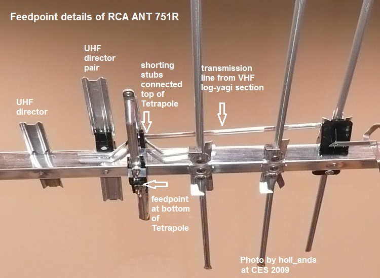
That is correct. The VHF section is missing one director, the UHF driven element is a straight dipole instead of the Tetrapole, the 4 shorting stubs that act as a UVSJ have been replaced with a pair of thin wires, and the first director in front of the UHF driven element is a straight strip instead of a director pair.
The Tetrapole was invented by John Winegard, and he used side-by-side director pairs in his patent.


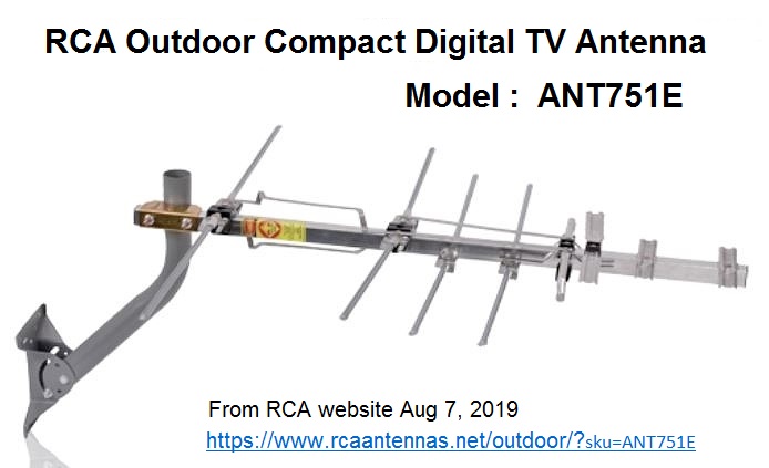
In the current 751E, they went back to the original design:

GroundUrMast is correct. The center of parasitic elements (director and reflector) can be attached to the boom because that is a zero voltage point; it doesn't affect the performance of a Yagi antenna.
However, the VHF section of the 751E is a hybrid design. The two rear VHF elements are a Log Periodic design that are connected together and then connected to the top of the UHF Tetrapole driven element where they are combined with the UHF signals. The front two VHF elements are parasitic Yagi director elements to increase VHF gain and can be fastened to the boom without harm. That is why the VHF section is called a Log-Yagi.
Last edited by rabbit73; 7-Aug-2019 at 8:25 PM.
|

|

|
 7-Aug-2019, 7:50 PM
|
#15
|
|
Retired A/V Tech
Join Date: Aug 2012
Location: S.E. VA
Posts: 2,750
|
Quote:
Originally Posted by RMinNJ

A bit off topic but out of curiosity I had picked up an ANT751r (longer box) having read here that its VHF would be better than the ANT751e (shorter box but blue) i tried.
|
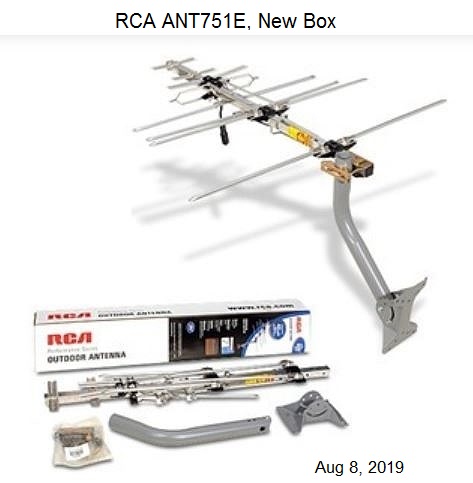
I think you are right about a new box for the 751E.

Is the box shown above the same as the one you got with your antenna?
Last edited by rabbit73; 7-Aug-2019 at 9:05 PM.
|

|

|
 7-Aug-2019, 7:52 PM
|
#16
|
|
Member
Join Date: Nov 2010
Posts: 54
|
Wow! This is more complicated than I had imagined!
|

|

|
 7-Aug-2019, 8:06 PM
|
#17
|
|
Retired A/V Tech
Join Date: Aug 2012
Location: S.E. VA
Posts: 2,750
|
Uh-Oh, have I overloaded your input?
Don't let it bother you. The correct solution is whatever works best for you
RCA made it more complicated when they used the same model number for different antennas. It's been hard for me to keep track of it. I started experimenting with antennas when I was 8; I'm 86 now, and still learning. 
Is that the box you got with your antenna that is shown above?
Last edited by rabbit73; 7-Aug-2019 at 8:43 PM.
|

|

|
 7-Aug-2019, 8:17 PM
|
#18
|
|
Retired A/V Tech
Join Date: Aug 2012
Location: S.E. VA
Posts: 2,750
|
Quote:
Originally Posted by freetvplease

My next experiment is to combine the 751 with the HDB4X and see if the VHF gain from both helps each other.
|
The HDB4X is sold as a VHF/UHF antenna, but it is primarily a UHF antenna that will pick up VHF signals if they are very strong.
If you combine the 751 and the HDB4X with a splitter in reverse, you will most likely have problems because the VHF signals picked up by the two antennas will interfere with each other at the combining point. The UHF signals from each will also interfere with each other.
If you want to use the 751 just for VHF and combine it with the HDB4X for UHF, that will work if you use a UVSJ (UHF-VHF-Separator-Joiner) to combine them. That is what GroundUrMast suggested in post #4.
Since you haven't included a signal report in this thread or told us what channels are most important to you, it isn't possible to tell you what setup might work best for your location.
Last edited by rabbit73; 7-Aug-2019 at 8:41 PM.
|

|

|
 7-Aug-2019, 9:17 PM
|
#19
|
|
Member
Join Date: Nov 2010
Posts: 54
|
Rabbit, I'm just messing around with this scenario because it's just an interest I have. My main antenna setup is the DB8e combined with the Y10-7-13 35 feet in the air which does an awesome job for me although I probably should pull it down and put either a UVSJ or a AD VHF/UHF combiner instead of the splitter I used in reverse. It's been working for over 5 years as is so why fix what ain't broke.
|

|

|
 7-Aug-2019, 9:29 PM
|
#20
|
|
Member
Join Date: Feb 2019
Posts: 35
|
Quote:
Originally Posted by rabbit73

I think you are right about a new box for the 751E.

Is the box shown above the same as the one you got with your antenna? |
The box was blue in color instead of white ...but shorter like the picture and the antennna boom came in 2 pieces like that. The ANT751r was a longer white box with the boom in one long piece.
|

|

|
 Posting Rules
|
You may not post new threads
You may not post replies
You may not post attachments
You may not edit your posts
HTML code is Off
|
|
|
|
|

