 |
|
 22-Apr-2020, 12:36 PM
|
#21
|
|
Antenna Enthusiast
Join Date: Mar 2016
Location: Beach Park IL
Posts: 318
|
16 Director Mod
After disappointing results adding four elements on to the existing factory antenna (Mod 1), I figured it was time to go for broke. I was already geared up to go further anyhow.
Mod 2. I sacrificed one of the reflectors from one the donor antennas and cut 4 new directors to continue the pattern. So, the last 6 directors are all 21" and spaced 10.5" Without any specific antenna modeling it seemed like like a logical step.
I sleeved the inside of the boom with "U" (technically C-Channel) and laid it on the 3/4" under support which I had left extended on the first mod, I figure it would come in hand and it did. I also fabricated a tab so I could attach the upper support cable to the end. The cable is pulled fairly tight. It is fairly solid and withstood 45 mile an hour winds already.
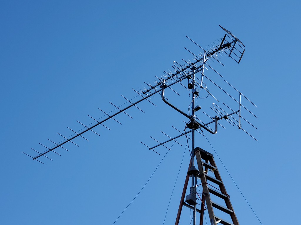
I wanted to put the boom attachment clamp closer to the center of the antenna but my reinforcements don't allow for that. I'll have to research adjustable beam clamps or, of course fabricate my own.
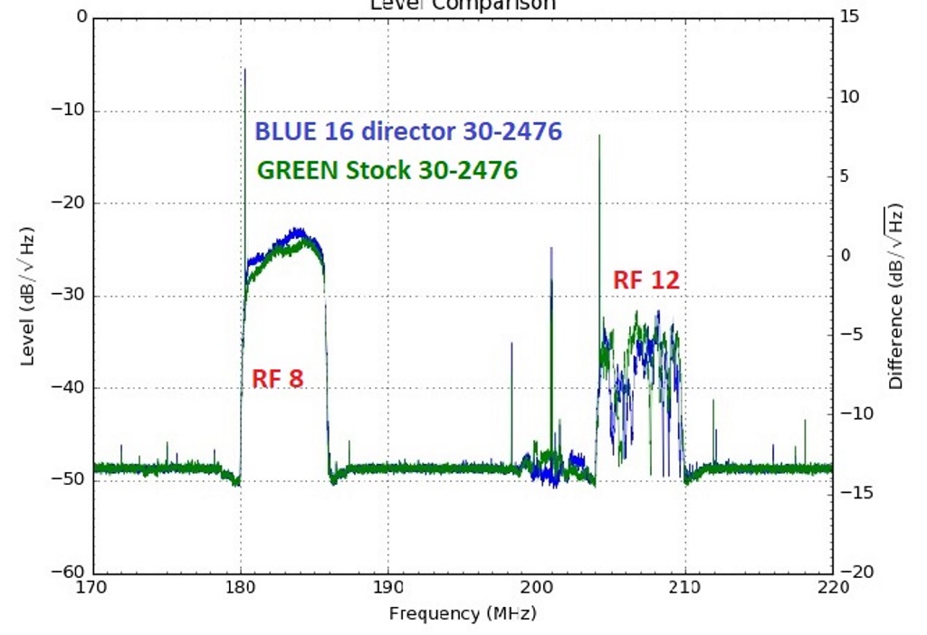
Testing: So-so results. After several comparative tests, I believe these will be the most consistent results. Maximum delta measured was + 2.84 dB. Overall, it's more like 1.2 dB and at the very end the two patterns seem to blend. RF12 is not in the antenna aim market, it is being picked up from the back of the antenna.
Last edited by bobsgarage; 22-Apr-2020 at 9:53 PM.
|

|

|
 22-Apr-2020, 6:50 PM
|
#22
|
|
Senior Member
Join Date: Nov 2014
Location: Acworth, GA
Posts: 291
|
You might want to use a Yagi calculator such as the one below to give you some ideas. Normally each director (also known as parasitic) element of a Yagi antenna will decrease in length the further it is from the driven element. They will also get further apart as the distance from the driven element increases. If you are looking for an antenna specifically for RF 8, try modeling a 17 element yagi at 183 MHz using the calculator and compare the results to what you have.
https://www.changpuak.ch/electronics...enna_DL6WU.php
__________________
Antennacraft Y10-7-13 VHF, Antennas Direct 91XG UHF
|

|

|
 22-Apr-2020, 10:57 PM
|
#23
|
|
Antenna Enthusiast
Join Date: Mar 2016
Location: Beach Park IL
Posts: 318
|
Good info.
Quote:
Originally Posted by Tim

You might want to use a Yagi calculator such as the one below to give you some ideas. Normally each director (also known as parasitic) element of a Yagi antenna will decrease in length the further it is from the driven element. They will also get further apart as the distance from the driven element increases. If you are looking for an antenna specifically for RF 8, try modeling a 17 element yagi at 183 MHz using the calculator and compare the results to what you have.
https://www.changpuak.ch/electronics...enna_DL6WU.php |
Hi Tim,
Thanks for the information.
Not specifically RF 8 that I'm after, it's just a transmitter I am using to measure my results. One reason is it is at least 49 miles away and makes it a far enough target. I could turn the antenna around and check RF12 also, but for now I like RF 8 because soon trees will leaf out in the path of RF12 and would destroy my baselines. I will test RF 12 soon enough though. before the leaves!
I don't know how to use the modeling software, I hear it is extremely tedious. I'm willing to learn it but I may have to do it later. I am hoping to find that someone has already tried this. I sent Holl_ands a PM but no reply. He has done the modeling but no mods so far that I know of.
What you did say was the director should begin to taper down and the spacing should widen. That is also of interest to me.
I did go to the link you sent, The picture show something similar to mine actually with some broken elements. The calculator is there, and although I can change the # of elements, parasitic elements and diameter of the boom, I click on "Show me the details" The boom should be 7.29 meters ! 14.20dB of gain. Nice.
Can I choose the length of boom I want? And then build it from there?
Some other questions.
What is an isolated Element?
Reflector? What to do with that?
Would I change my Dipole dimensions?
BTW, 26' 7" for a 17 element at 183 MHz whoa!
Last edited by bobsgarage; 23-Apr-2020 at 12:00 AM.
|

|

|
 22-Apr-2020, 11:48 PM
|
#24
|
|
Antenna Enthusiast
Join Date: Mar 2016
Location: Beach Park IL
Posts: 318
|
183 MHz
Frequency : 183 MHz
Wavelength : 1639 mm
Rod Diameter : 10 mm
Boom Diameter : 18 mm
Boom Length : 7290 mm
d/lambda : 0.006 ( min.: 0.002 , max.: 0.01 )
D/lambda : 0.011 ( min.: 0.01 , max.: 0.05 )
Elements : 16
Gain : 14.20 dBd (approx.)
-------------------------------------------------------------
Reflector Length : 790 mm
Reflector Position : 0 mm
-------------------------------------------------------------
Dipole Position : 393 mm
-------------------------------------------------------------
Director #1 Position : 516 mm , Length : 745 mm
Distance Dipole - Dir. #1 : 123 mm
-------------------------------------------------------------
Director #2 Position : 811 mm , Length : 738 mm
Distance Dir. #1 - Dir. #2 : 295 mm
-------------------------------------------------------------
Director #3 Position : 1164 mm , Length : 732 mm
Distance Dir. #2 - Dir. #3 : 352 mm
-------------------------------------------------------------
Director #4 Position : 1574 mm , Length : 726 mm
Distance Dir. #3 - Dir. #4 : 410 mm
-------------------------------------------------------------
Director #5 Position : 2033 mm , Length : 720 mm
Distance Dir. #4 - Dir. #5 : 459 mm
-------------------------------------------------------------
Director #6 Position : 2525 mm , Length : 715 mm
Distance Dir. #5 - Dir. #6 : 492 mm
-------------------------------------------------------------
Director #7 Position : 3041 mm , Length : 711 mm
Distance Dir. #6 - Dir. #7 : 516 mm
-------------------------------------------------------------
Director #8 Position : 3582 mm , Length : 707 mm
Distance Dir. #7 - Dir. #8 : 541 mm
-------------------------------------------------------------
Director #9 Position : 4148 mm , Length : 704 mm
Distance Dir. #8 - Dir. #9 : 566 mm
-------------------------------------------------------------
Director #10 Position : 4738 mm , Length : 700 mm
Distance Dir. #9 - Dir. #10 : 590 mm
-------------------------------------------------------------
Director #11 Position : 5352 mm , Length : 698 mm
Distance Dir. #10 - Dir. #11 : 615 mm
-------------------------------------------------------------
Director #12 Position : 5984 mm , Length : 695 mm
Distance Dir. #11 - Dir. #12 : 631 mm
-------------------------------------------------------------
Director #13 Position : 6623 mm , Length : 693 mm
Distance Dir. #12 - Dir. #13 : 639 mm
-------------------------------------------------------------
Director #14 Position : 7270 mm , Length : 691 mm
Distance Dir. #13 - Dir. #14 : 648 mm
-------------------------------------------------------------
Directors / Parasitics are isolated.
Please choose an isolater thicker than : 9 mm
|

|

|
 22-Apr-2020, 11:49 PM
|
#25
|
|
Antenna Enthusiast
Join Date: Mar 2016
Location: Beach Park IL
Posts: 318
|
220 Mhz
Frequency : 220 MHz
Wavelength : 1364 mm
Rod Diameter : 10 mm
Boom Diameter : 18 mm
Boom Length : 6068 mm
d/lambda : 0.007 ( min.: 0.002 , max.: 0.01 )
D/lambda : 0.013 ( min.: 0.01 , max.: 0.05 )
Elements : 16
Gain : 14.20 dBd (approx.)
-------------------------------------------------------------
Reflector Length : 663 mm
Reflector Position : 0 mm
-------------------------------------------------------------
Dipole Position : 327 mm
-------------------------------------------------------------
Director #1 Position : 430 mm , Length : 625 mm
Distance Dipole - Dir. #1 : 102 mm
-------------------------------------------------------------
Director #2 Position : 675 mm , Length : 619 mm
Distance Dir. #1 - Dir. #2 : 245 mm
-------------------------------------------------------------
Director #3 Position : 968 mm , Length : 614 mm
Distance Dir. #2 - Dir. #3 : 293 mm
-------------------------------------------------------------
Director #4 Position : 1309 mm , Length : 609 mm
Distance Dir. #3 - Dir. #4 : 341 mm
-------------------------------------------------------------
Director #5 Position : 1691 mm , Length : 605 mm
Distance Dir. #4 - Dir. #5 : 382 mm
-------------------------------------------------------------
Director #6 Position : 2100 mm , Length : 600 mm
Distance Dir. #5 - Dir. #6 : 409 mm
-------------------------------------------------------------
Director #7 Position : 2530 mm , Length : 597 mm
Distance Dir. #6 - Dir. #7 : 430 mm
-------------------------------------------------------------
Director #8 Position : 2980 mm , Length : 593 mm
Distance Dir. #7 - Dir. #8 : 450 mm
-------------------------------------------------------------
Director #9 Position : 3450 mm , Length : 591 mm
Distance Dir. #8 - Dir. #9 : 470 mm
-------------------------------------------------------------
Director #10 Position : 3941 mm , Length : 588 mm
Distance Dir. #9 - Dir. #10 : 491 mm
-------------------------------------------------------------
Director #11 Position : 4452 mm , Length : 586 mm
Distance Dir. #10 - Dir. #11 : 511 mm
-------------------------------------------------------------
Director #12 Position : 4977 mm , Length : 584 mm
Distance Dir. #11 - Dir. #12 : 525 mm
-------------------------------------------------------------
Director #13 Position : 5509 mm , Length : 582 mm
Distance Dir. #12 - Dir. #13 : 532 mm
-------------------------------------------------------------
Director #14 Position : 6048 mm , Length : 580 mm
Distance Dir. #13 - Dir. #14 : 539 mm
-------------------------------------------------------------
Directors / Parasitics are not isolated.
The length has been increased to compensate for that.
|

|

|
 23-Apr-2020, 3:48 AM
|
#26
|
|
Senior Member
Join Date: Nov 2014
Location: Acworth, GA
Posts: 291
|
The answer to your questions is below in blue. I have only built one Yagi for TV and that was years ago and it worked very well pulling in a weak station (before the days of digital TV). I have used several for VHF and UHF ham radio bands.
Quote:
Originally Posted by bobsgarage

Can I choose the length of boom I want? And then build it from there?
It is calculating the minimum length of the boom to match the number of elements you specify. Try changing the number of elements until you reach a point that will fit on the boom length you have available.
Some other questions.
What is an isolated Element?
It is asking are the elements directly connected to the boom (metal to metal) or are the elements insulated from the boom (isolated)
Reflector? What to do with that?
The reflector is the element mounted behind the driven element, in your case you have four reflectors mounted on a vertical boom at the rear of your antenna. The calculated reflector length would be a good starting point for each of your reflector elements. You could probably even replace the reflector assembly you have now with just one reflector element.
Would I change my Dipole dimensions?
Most likely you might need to. Your driven element is a folded dipole configuration because it provides an impedence of about 300 ohms, which works very well when using a 4:1 balun. There is another calculator you can use for that: https://www.changpuak.ch/electronics/Dipole_folded.php
BTW, 26' 7" for a 17 element at 183 MHz whoa!
Keep in mind that a Yagi antenna has a bandwidth of 2 to 3 percent of its design frequency, so a Yagi designed for 183 MHz will only cover enough frequency range for 1 TV channel. They are great and high gain but only when you are looking for one specific channel. |
__________________
Antennacraft Y10-7-13 VHF, Antennas Direct 91XG UHF
|

|

|
 23-Apr-2020, 1:01 PM
|
#27
|
|
Antenna Enthusiast
Join Date: Mar 2016
Location: Beach Park IL
Posts: 318
|
Thanks Tim, I'll look at that dipole calculator.
Quote:
|
Keep in mind that a Yagi antenna has a bandwidth of 2 to 3 percent of its design frequency, so a Yagi designed for 183 MHz will only cover enough frequency range for 1 TV channel. They are great and high gain but only when you are looking for one specific channel.*
|
How do I specify if I'm building an antenna for all hi VHF channels RF 7 - RF 13 ?
Again thanks for the info you just made it interesting for me!
Last edited by bobsgarage; 23-Apr-2020 at 1:09 PM.
|

|

|
 24-Apr-2020, 3:17 AM
|
#28
|
|
Senior Member
Join Date: Nov 2014
Location: Acworth, GA
Posts: 291
|
Quote:
Originally Posted by bobsgarage

Thanks Tim, I'll look at that dipole calculator.
How do I specify if I'm building an antenna for all hi VHF channels RF 7 - RF 13 ?
Again thanks for the info you just made it interesting for me!
|
Unfortunately you can't with that particular calculator. For channels 7 to 13 you'll need to cover a range from 174 to 216 MHz which is probably not possible with a Yagi (that I am aware of).
You might want to check out a log periodic antenna. Enter your min and max frequency and maximum boomlength into this calculator ( https://www.changpuak.ch/electronics/lpda.php) and see what you come up with. You could probably get about 10 or 11 dB of gain on a 12 ft boom with about 15 elements.
__________________
Antennacraft Y10-7-13 VHF, Antennas Direct 91XG UHF
|

|

|
 24-Apr-2020, 4:44 AM
|
#29
|
|
Antenna Enthusiast
Join Date: Mar 2016
Location: Beach Park IL
Posts: 318
|
Thank you again Tim.
So, because I would have to start completely over to build a log periodic it looks like I probably won't do that right now. I guess I would be a project for another day.
So speaking of the out of the box HI VHF yagi antennas. Are they generally designed for the middle of the spectrum? I mean how does the company come up with an antenna like the 30-2476 that performs well across the VHF High Spectrum?
Last edited by bobsgarage; 24-Apr-2020 at 12:16 PM.
|

|

|
 24-Apr-2020, 6:34 PM
|
#30
|
|
Senior Member
Join Date: Nov 2014
Location: Acworth, GA
Posts: 291
|
Quote:
Originally Posted by bobsgarage

Thank you again Tim.
So, because I would have to start completely over to build a log periodic it looks like I probably won't do that right now. I guess I would be a project for another day.
So speaking of the out of the box HI VHF yagi antennas. Are they generally designed for the middle of the spectrum? I mean how does the company come up with an antenna like the 30-2476 that performs well across the VHF High Spectrum?
|
Well, that is a question that is beyond my abilities to answer. My VHF antenna experience has been with ham radio antennas where the entire band is only 4 to 5 MHz wide. Narrowband Yagis are widely used because of their high gain and narrow bandwidth. Great if you only need to receive one TV channel, not so much if you want to receive the entire VHF-Hi band.
I would speculate that building an antenna to cover a band 42 MHz wide is much more complicated.
Have you ever taken a look at this web page that has a lot of info about a number of different antenna types?
https://imageevent.com/holl_ands;jse...s441x1hne1.dog
__________________
Antennacraft Y10-7-13 VHF, Antennas Direct 91XG UHF
|

|

|
 24-Apr-2020, 9:38 PM
|
#31
|
|
Antenna Enthusiast
Join Date: Mar 2016
Location: Beach Park IL
Posts: 318
|
Quote:
Originally Posted by Tim

Well, that is a question that is beyond my abilities to answer. My VHF antenna experience has been with ham radio antennas where the entire band is only 4 to 5 MHz wide. Narrowband Yagis are widely used because of their high gain and narrow bandwidth. Great if you only need to receive one TV channel, not so much if you want to receive the entire VHF-Hi band.
I would speculate that building an antenna to cover a band 42 MHz wide is much more complicated.
Have you ever taken a look at this web page that has a lot of info about a number of different antenna types?
https://imageevent.com/holl_ands;jse...s441x1hne1.dog |
Hi Tim, I know it's complicated. I appreciate your help. So yes I'm familiar with Holl_ands, he's an antenna modeling Guru. I tried to contact him, maybe he'll contact me.
|

|

|
 8-May-2020, 5:22 PM
|
#32
|
|
Antenna Enthusiast
Join Date: Mar 2016
Location: Beach Park IL
Posts: 318
|
Quote:
Originally Posted by Tim

Well, that is a question that is beyond my abilities to answer. My VHF antenna experience has been with ham radio antennas where the entire band is only 4 to 5 MHz wide. Narrowband Yagis are widely used because of their high gain and narrow bandwidth. Great if you only need to receive one TV channel, not so much if you want to receive the entire VHF-Hi band.
I would speculate that building an antenna to cover a band 42 MHz wide is much more complicated.
Have you ever taken a look at this web page that has a lot of info about a number of different antenna types?
https://imageevent.com/holl_ands;jse...s441x1hne1.dog |
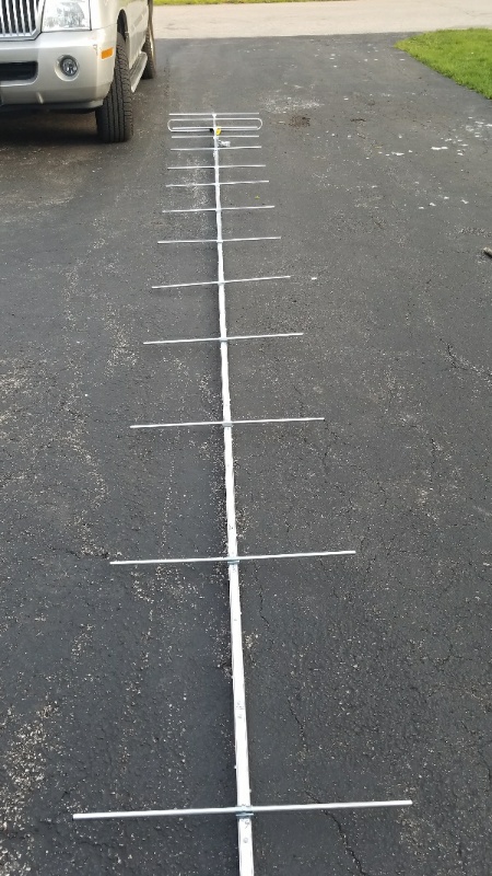
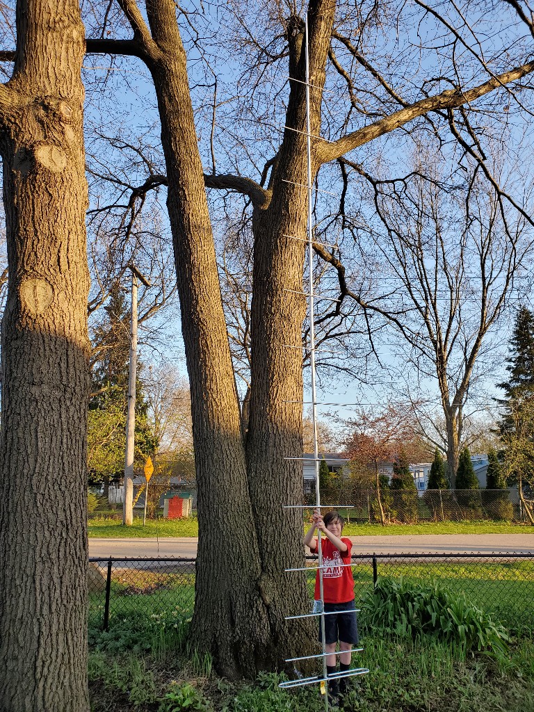
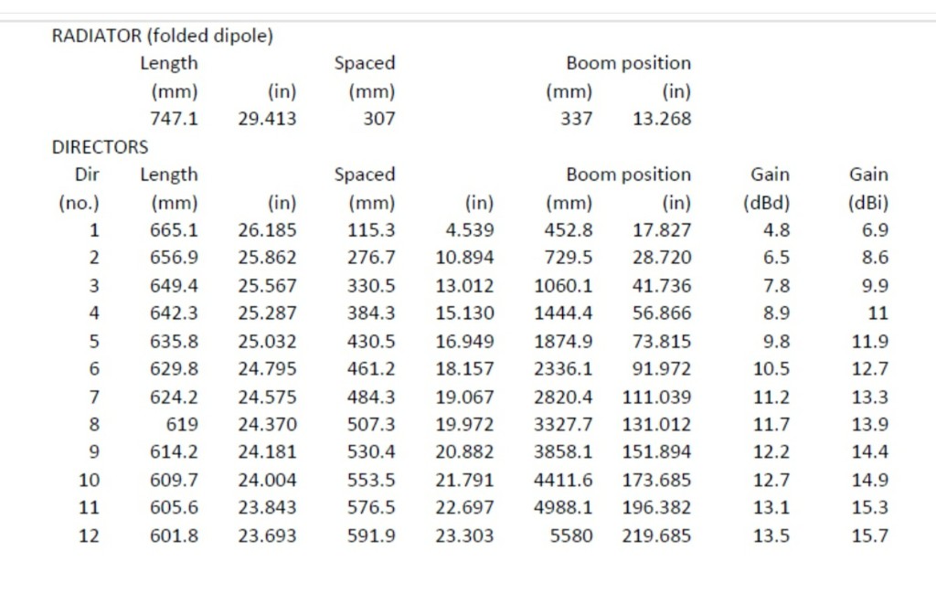
Tim, Tripleo, I'm going to call this MOD 4, here's what I went with, from Tom Ballister:
Last edited by bobsgarage; 9-May-2020 at 4:20 AM.
|

|

|
 9-May-2020, 7:31 PM
|
#33
|
|
Senior Member
Join Date: Nov 2014
Location: Acworth, GA
Posts: 291
|
Quote:
Originally Posted by bobsgarage

Tim, Tripleo, I'm going to call this MOD 4, here's what I went with, from Tom Ballister:
|
Very nice! Let us know how it works.
__________________
Antennacraft Y10-7-13 VHF, Antennas Direct 91XG UHF
|

|

|
 10-May-2020, 12:14 PM
|
#34
|
|
Antenna Enthusiast
Join Date: Mar 2016
Location: Beach Park IL
Posts: 318
|
Quote:
Originally Posted by Tim

Very nice! Let us know how it works.
|
I'll let you know when it might be a couple days before the weather permits me to go back outside and work on it. The antenna itself is done , however it's going to need quite a bit of bracing. It is 18.3 feet long.
I did pick up a 20-foot piece of one inch by 1 inch aluminum square tubing with a .125 wall. But the 20 foot piece actually sags under its own weight. Since this antennas and odd design , I will probably come up with an odd brace.
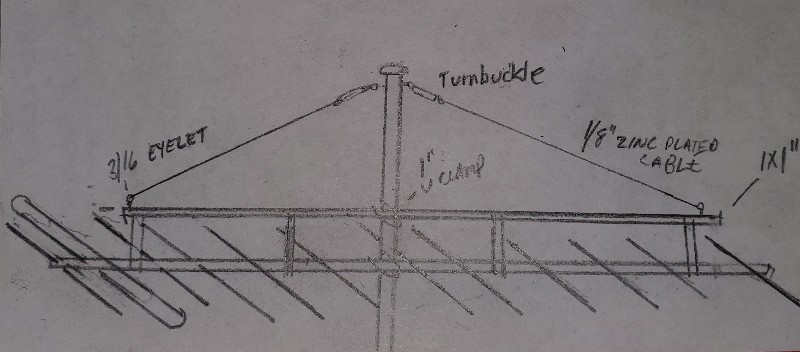
Not long ago I saw an antenna on a roof and the boom brace was above the antenna boom. Is there any anything wrong with doing it that way? That opens up couple possibilities if I can do that.
Last edited by bobsgarage; 12-May-2020 at 5:17 PM.
|

|

|
 10-May-2020, 5:28 PM
|
#35
|
|
Senior Member
Join Date: Nov 2014
Location: Acworth, GA
Posts: 291
|
Quote:
Originally Posted by bobsgarage

Not long ago I saw an antenna on a roof and the boom brace was above the antenna boom. Is there any anything wrong with doing it that way? That opens up couple possibilities if I can do that.
|
I have seen a number of antennas constructed in that manner. I doubt that it makes any substantial difference.
__________________
Antennacraft Y10-7-13 VHF, Antennas Direct 91XG UHF
|

|

|
 15-May-2020, 2:40 PM
|
#36
|
|
Antenna Enthusiast
Join Date: Mar 2016
Location: Beach Park IL
Posts: 318
|
VHF super-long yagi
Quote:
Originally Posted by Tim

I have seen a number of antennas constructed in that manner. I doubt that it makes any substantial difference.
|
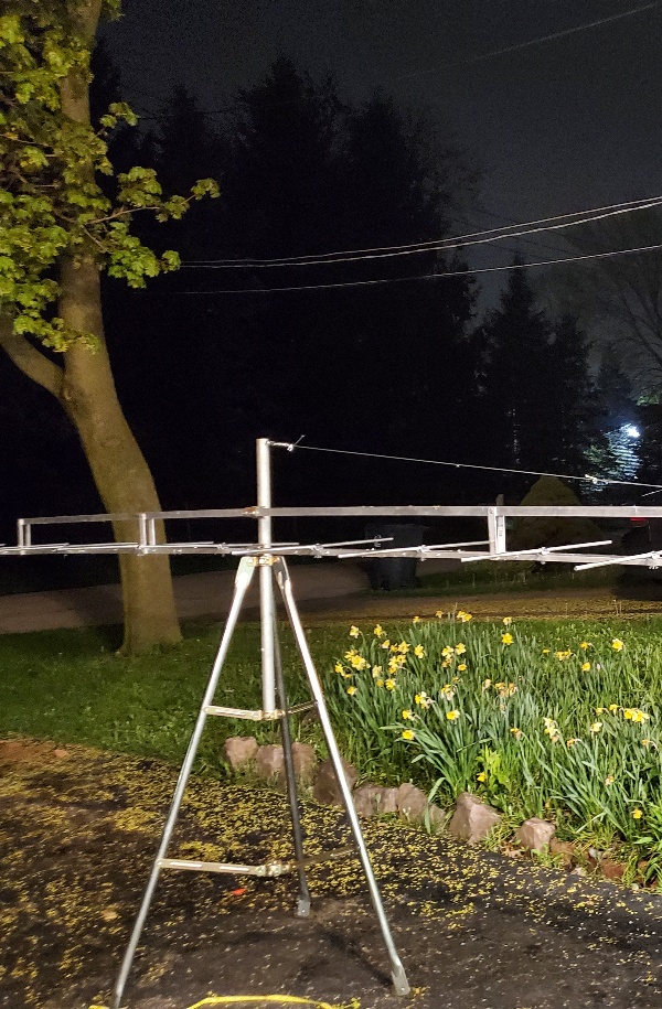
Triple O and Tim and whoever else is following this with interest. We had the best weather yesterday after the storms went through. However it wasn't the end of the rains but I had a full three or four hour window to get my 18' long yagi braced up with a over the boom support. I cut the 1in by 1in support down to about 12 and a half feet and riveted upright flat stock braces:
I want to say thanks to you guys so far for keeping the interest this project.
I haven't put it in the air yet, probably this weekend.

Last edited by bobsgarage; 15-May-2020 at 4:27 PM.
|

|

|
 15-May-2020, 6:08 PM
|
#37
|
|
Senior Member
Join Date: Nov 2014
Location: Acworth, GA
Posts: 291
|
It has been a very interesting project. Thanks for keeping us updated and sharing the photos.
__________________
Antennacraft Y10-7-13 VHF, Antennas Direct 91XG UHF
|

|

|
 16-May-2020, 8:12 PM
|
#38
|
|
Antenna Enthusiast
Join Date: Mar 2016
Location: Beach Park IL
Posts: 318
|
Project braced.
Quote:
Originally Posted by Tim

It has been a very interesting project. Thanks for keeping us updated and sharing the photos.
|
One more, before she goes up in the air, today!!

Hey, you guys ! I over calculated the boom length. There is an extra 20" or so... I wonder if it would hurt to add another director?? I won't do it now. Food for thought though.
Last edited by bobsgarage; 18-May-2020 at 5:22 PM.
|

|

|
 27-May-2020, 5:33 AM
|
#39
|
|
Antenna Enthusiast
Join Date: Mar 2016
Location: Beach Park IL
Posts: 318
|
30-2476 MOD 4 Modeled Yagi
Last edited by bobsgarage; 27-May-2020 at 5:46 PM.
|

|

|
 27-May-2020, 6:29 AM
|
#40
|
|
Antenna Enthusiast
Join Date: Mar 2016
Location: Beach Park IL
Posts: 318
|
30-2476 MOD 5 Modeled Yagi VHF
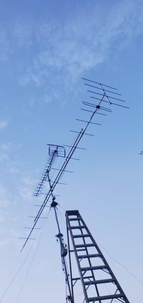
All I did was put the reflector from another 30-2476 on this new Super Long Yagi. I had to remove the single reflector and put the 4 reflector on:
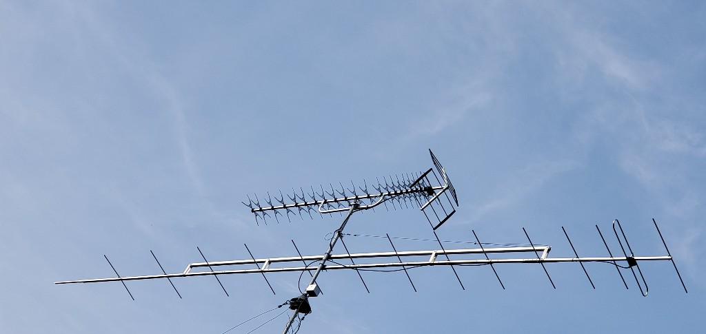
Not much of a change, also, in the notation under RF8 Milwaukee, it says "Chicago", disregard that it should say that under RF12, oops:

Getting some usable UHF ! :

Last edited by bobsgarage; 27-May-2020 at 1:53 PM.
|

|

|
 Posting Rules
|
You may not post new threads
You may not post replies
You may not post attachments
You may not edit your posts
HTML code is Off
|
|
|
|
|

