Quote:
|
what parameters in the simulation software would need to be altered to lift the lobes of reception and decrease the SWR?
|
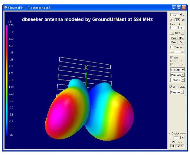
GroundUrMast had to select a frequency to model the antenna; he picked 584 MHz in the middle of the UHF band. Each dipole is 32" wide. That would make a halfwave dipole for 173 MHz, which is just below CH7. It would make a fullwave dipole (like for a bowtie antenna) for 346 MHz, which is between VHF-High and UHF.
The downward tilt is probably because the feed point is at the bottom. A downward tilt is used by TV transmitting antennas because the receiving antennas are usually at a lower elevation.
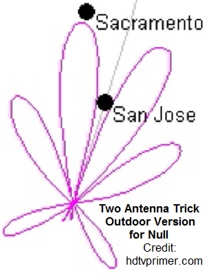
The main lobe is split in two because the two sides are out of phase as they would be with two antennas stacked side-by-side and fed out of phase to produce a null between the lobes. This is useful when you want to receive weak signals that are almost in the same direction as the local strong signals. It is called the Two-Antenna-Trick on hdtvprimer.com.

Quote:
|
Is there any proven correlation between the software and real life design and reception?
|
Oh, yes. First you have an idea, then you model it at the desired design frequency, and then you build the antenna and test it for proof of performance.
Most antennas can be modeled with the free software. Very complicated antennas require expensive software for accurate modeling.
Quote:
|
Shouldn't the whole surface of the antenna design generate some current since wave reception occurs throughout surface area?
|
The model is already making that assumption. In real use, the whole surface of the antenna might not be receiving an equal signal, this is called a non-uniform field.
You can see it happen when you move an antenna to a hot spot and note the increase in signal strength.

