 |
 31-Dec-2015, 3:23 AM
|
#1
|
|
Junior Member
Join Date: Dec 2015
Posts: 13
|
Stacked antenna in a very weak signal area
I currently have an HDB8X antenna at 15 feet up and no rotor, and it’s barely cutting it for me.
I’m looking into taking this down, in favor of a pair of 91XG’s stacked. I’m currently using a CM-7777 preamp, with no splitters.
I have noise margins that range from -10, to -15 for the signals that I want the most.
So with this in mind, I have a few questions:
A) I’ve read a few different places about the spacing, for identical stacked antennas. 3 feet, or 25 inches. What is the ideal spacing?
B) What are my chances of getting the signals with the lowest noise margins? I’ve done my research about needing a NM above 0 to get a channel, or above 5 for a solid picture in all conditions.
C) What do I expect to see in gain from both of them vs one? I’ve heard that you add 3 dB, to what you’d get with a single XG91. Is this correct?
The current antenna gets 2(25), 6 (34), 8(8), and 19(27) solid 24/7. 4(51), 11(48), 16(38), 22(42), and 53(43) depend on the conditions.
The stations I really hope to get are 4 (51), 11 (48), 22(42) and 53 (43). Getting 16 (38) and RF 19 (WEMW – repeater out of Greensburg ) would be nice, but don’t expect it. 8 is the only VHF I care about, but I figure with a NM of +23, and 25 miles away, that getting it shouldn’t be a problem.
Any help and information would be very appreciated!!
TV Fool report:
http://www.tvfool.com/?option=com_wr...b97db7431787c0
(Ignore WPXI RF21, transmitter was never built)
|

|

|
|
31-Dec-2015, 11:20 PM
|
#2
|
|
Retired A/V Tech
Join Date: Aug 2012
Location: S.E. VA
Posts: 2,747
|
Welcome, rockin1jr:
Quote:
|
A) I’ve read a few different places about the spacing, for identical stacked antennas. 3 feet, or 25 inches. What is the ideal spacing?
|
For horizontal stacking, Calaveras knows more about it than anyone I know. I suggest you go to AVS and get his attention.
http://www.avsforum.com/forum/25-hdtv-technical/
His 91XGs looks like this:
http://www.aa6g.org/DTV/index.html
and his antenna system diagram is here:
http://www.aa6g.org/DTV/ABD/Antenna_Block_Diagram.html
I suggest you try just one 91XG at first for a comparison with your HDB8X. One 91XG has a narrow horizontal beamwidth, so azimuth aim is critical. For best results, the antenna must be aimed directly at the transmitter. You will not be able to "split the difference."
The next step up would be to stack two 91XGs. With two 91XGs, aim is even more critical. You can use a splitter in reverse as a combiner. The two coax lines must be the same length.
To keep losses low, Calaveras is using halfwave coaxial baluns, and combining the two antennas in parallel, giving 37.5 ohms, which is converted to 75 ohms by a quarter wave 50 ohm matching section. Any losses before the input of the preamp directly reduce the antenna gain. Losses after the preamp are less harmful because of the Friis Cascaded Noise Figure Equation that says the preamp NF primarily determines the system noise figure.
Quote:
|
B) What are my chances of getting the signals with the lowest noise margins? I’ve done my research about needing a NM above 0 to get a channel, or above 5 for a solid picture in all conditions.
|
The 0 dB NM on the tvfool report is based upon a dipole antenna (0 dBd). You can add antenna gain and preamp gain to make the NM more positive, but you must subtract the preamp NF.
For reliable reception you should add a "fade margin" of 10 dB because OTA signals constantly vary in strength, but I doubt that you will have that luxury with the very weak signals you want.
Last edited by rabbit73; 1-Jan-2016 at 12:33 AM.
|
|
|
|
|
31-Dec-2015, 11:39 PM
|
#3
|
|
Retired A/V Tech
Join Date: Aug 2012
Location: S.E. VA
Posts: 2,747
|
Quote:
|
I have noise margins that range from -10, to -15 for the signals that I want the most.
|
Special effort is required to receive weak signals with a negative Noise Margin.
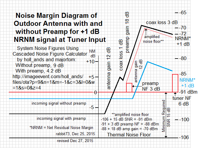
Without a preamp, signals below NM -2 dB with an antenna gain of 12 dB can not be received because of the tuner NF that is added to the thermal noise floor and the minimum required SNR of 15 dB.
With a preamp, the antenna gain must bring the signal SNR up to at least the minimum required SNR plus the preamp NF BEFORE the preamp input, because the preamp NF makes the NM more negative.
Fortunately, the tvfool report has poor accuracy with 1 and 2Edge signals, and signals can often diffract over terrain interference and the curvature of the earth to arrive at your antenna.
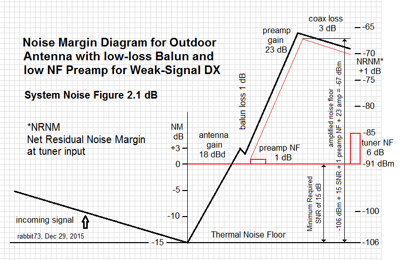
You need a way to measure your progress, to tell you if more effort and expense are justified. A SiliconDust HDHR can give you SNR, which they call signal quality. My Sony TV gives SNR as low as 13 dB on the Diagnostics Screen, but only if it has picked up the channel. You could get your system noise figure down to about 1 dB if you use a halfwave coaxial balun and a preamp with a NF of 0.4 dB.

Quote:
|
C) What do I expect to see in gain from both of them vs one? I’ve heard that you add 3 dB, to what you’d get with a single XG91. Is this correct?
|
The theory says 3 dB, but there are combining losses. When you use a splitter in reverse as a combiner, it has an internal loss of 0.5 dB, so the most I have been able to get is 2.5 dB gain.
Quote:
|
I currently have an HDB8X antenna at 15 feet up and no rotor, and it’s barely cutting it for me.
|
Any chance of getting it higher? Does your tvfool report look any better higher?
Are there any trees or other buidings in the signal path?
Last edited by rabbit73; 11-Sep-2017 at 10:35 PM.
|
|
|
|
|
1-Jan-2016, 2:36 PM
|
#4
|
|
Junior Member
Join Date: Dec 2015
Posts: 13
|
Thanks rabbit73 for your reply and information.
Quote:
Originally Posted by rabbit73

Any chance of getting it higher? Does your tvfool report look any better higher?
|
If I do 50 feet, vs 20 feet, my NM for 11 (RF48) drops from 14.5 to 12. The problem with height is my mast (a piece of fence post from Lowes) is attached to the side of a garage, so I would have no support on it above 9 feet up.
Quote:
Originally Posted by rabbit73
Are there any trees or other buidings in the signal path?
|
No buildings, but there's a small ridge line about 20 miles out, plus a strong line of trees on the horizon.
|
|
|
|
|
1-Jan-2016, 2:46 PM
|
#5
|
|
Junior Member
Join Date: Dec 2015
Posts: 13
|
Quote:
Originally Posted by rabbit73
|
I was originally on AVS this past April 2015 when I was starting with my current set up. At that point in time, I was aiming for an 8 bay, and wasn't planning on a more expensive antenna till now.
I'll have to hop on there and send him a message, or create a similar thread.
Quote:
Originally Posted by rabbit73
I suggest you try just one 91XG at first for a comparison with your HDB8X. One 91XG has a narrow horizontal beamwidth, so azimuth aim is critical. For best results, the antenna must be aimed directly at the transmitter. You will not be able to "split the difference."
|
I already know about how sensitive a pair of 91XGs are when stacked. That's why I plan to put up a rotor, since some signals need the antenna pointed directly at them. And to take extra time to make sure their both pointed the same direction when mounted.
Quote:
Originally Posted by rabbit73
To keep losses low, Calaveras is using halfwave coaxial baluns, and combining the two antennas in parallel, giving 37.5 ohms, which is converted to 75 ohms by a quarter wave 50 ohm matching section. Any losses before the input of the preamp directly reduce the antenna gain. Losses after the preamp are less harmful because of the Friis Cascaded Noise Figure Equation that says the preamp NF primarily determines the system noise figure.
|
Are there any instructions on the internet on how to build the halfwave coaxial baluns, and how to combine the two antennas in parallel, giving 37.5 ohms, which is converted to 75 ohms by a quarter wave 50 ohm matching section?
Worst case snario, I'd buy a combiner and use that (with equal lengths of RG6 of course).
(I won't be doing this before April, just want to do my research now).
|
|
|
|
|
1-Jan-2016, 3:30 PM
|
#6
|
|
Retired A/V Tech
Join Date: Aug 2012
Location: S.E. VA
Posts: 2,747
|
Quote:
|
Are there any instructions on the internet on how to build the halfwave coaxial baluns
|
Plenty
https://www.google.com/?gws_rd=ssl#q...+coaxial+balun
https://www.google.com/search?q=half...0nCIQQ_AUIBygC
The coax balun would replace the balun that comes with the antenna. With two antennas they must be connected the same way to keep the signals in phase. It's a lot of trouble for a slight reduction in loss, and keeping the coax ends waterproof is a problem. If I made one I would use a metal plate with 3 chassis F connectors like at the bottom of the 7777 housing and the coax would dangle down from the bottom. As Calaveras says in his diagram, the combiner is merely the 3 pieces of coax soldered together. The 1/4 wave matching line is just a piece of 50 ohm coax 1/4 wave long taking the velocity factor into consideration as is done with the balun. I would look for an F connector T adapter to do it.
https://www.google.com/?gws_rd=ssl#q...ctor+T+adapter
Last edited by rabbit73; 1-Jan-2016 at 3:41 PM.
|
|
|
|
|
2-Jan-2016, 3:51 PM
|
#7
|
|
Junior Member
Join Date: Dec 2015
Posts: 13
|
Quote:
Originally Posted by rabbit73
Plenty
https://www.google.com/?gws_rd=ssl#q...+coaxial+balun
https://www.google.com/search?q=half...0nCIQQ_AUIBygC
The coax balun would replace the balun that comes with the antenna. With two antennas they must be connected the same way to keep the signals in phase. It's a lot of trouble for a slight reduction in loss, and keeping the coax ends waterproof is a problem. If I made one I would use a metal plate with 3 chassis F connectors like at the bottom of the 7777 housing and the coax would dangle down from the bottom. As Calaveras says in his diagram, the combiner is merely the 3 pieces of coax soldered together. The 1/4 wave matching line is just a piece of 50 ohm coax 1/4 wave long taking the velocity factor into consideration as is done with the balun. I would look for an F connector T adapter to do it.
https://www.google.com/?gws_rd=ssl#q...ctor+T+adapter |
Thanks for the info rabbit73. I think my noise margins are too low to make a stacked antenna a huge helper, especially with only default 2.5 dB gain (we get a ton of rain storms here April - September, so any homemade combiner would certinally get wet).
I decided to go with 1 XG91 and see how it does at 20 feet with a rotor. I imagine it would out preform my HDB8X, solely on the fact that I replaced the default combiner on it with a ChannelPlus combiner, to not block out my local Fox on VHF. This has to be giving it some loss.
But thanks again for the help.
|
|
|
|
|
2-Jan-2016, 4:25 PM
|
#8
|
|
Senior Member
Join Date: Dec 2009
Location: Delmar, NY
Posts: 1,236
|
I'd say that replacing antennas is unlikely to snag you any more stations. What you can try is to move the HDB8X antenna around to try to find an optimum height and aim plus try to avoid trees toward 242 degrees. Even then, I'd expect only 4 (51) to be the one extra station you might pick up.
In your location the angle up to the hills that block channel 51 are elevated 3.7 degrees. Theoretically, the optimum antenna heights to achieve a 3.7 degree take-off angle are 5.5' and 17'.
|
|
|
|
 Posting Rules
|
You may not post new threads
You may not post replies
You may not post attachments
You may not edit your posts
HTML code is Off
|
|
|
|
|


