Using an Attenuator to Measure the Strength of a Digital TV Signal, Part 2
I ordered a Mediasonic HW-150PVR and a Toner 0-20 dB Variable Attenuator to see how they would do at estimating the strength of a TV signal.
I had previously used a 0-10 dB step attenuator, but they are expensive; I was lucky to find a good used one. I'm trying to find the least expensive equipment to do the job.
I had also used an Antennas Direct 0-20 dB Variable Attenuator, but they have been discontinued along with their FM filter.
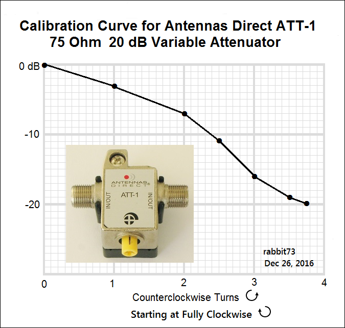

Since the AD ATT-1 was no longer available for others to buy, I made a calibration chart for the Toner attenuator:
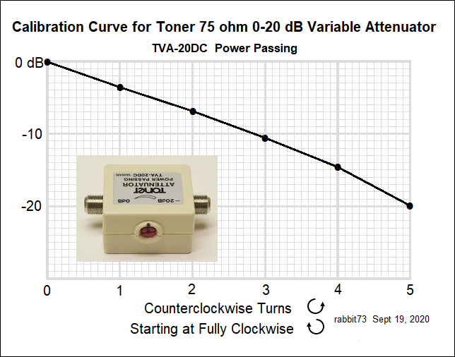
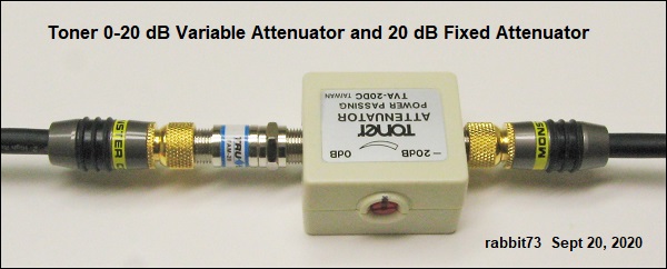
I don't know why the factory pasted the label on upside down.
I put a black mark on the knob and on the housing to be able to count the number of turns as I rotated the shaft counterclockwise with a screwdriver to increase the attenuation to dropout.
This was the setup:
Code:
                    Fixed       Variable                      SDR
Ant > 25 ft RG6 > Attenuator > Attenuator > 4-Way Splitter > HW-150
                    20 dB    at 1-1/2 turns                   SLM*
                                  5 dB                   75 ohm terminator
* SLM is Sadelco DisplayMax 800 Signal Level Meter

To find the signal strength of Channel 20, I added the attenuator setting to the average tuner dropout point of -85 dBm:
-85dBm + 25 dB =
-60 dBm
To confirm the method, my Sadelco DisplayMax Signal level meter reading was -11.9 dBmV =
-60.7 dBm
(Since I used a 4-Way splitter, the signal before the splitter was 7 dB stronger. I put a 75 Ohm terminator on the unused port because without it, the outputs weren't equal.)
This method works best on UHF. On VHF, where the noise level is higher, dropout will be higher than at -85 dBm.

The Thermal Noise Floor for a 6 MHz wide TV signal is about -106 dBm.
The Noise Figure for the average tuner is 6 dB:
-106 dBm + 6 dB = -100 dBm
To that we must add 15 dB to allow for the minimum required SNR for the TV signal:
-100 dBm + 15 dB = -85 dBm
However, if the ambient noise is stronger than the internal noise of the tuner, the tuner Noise will be buried in the ambient noise.