 |
|
 26-Jul-2017, 11:17 PM
|
#81
|
|
Retired A/V Tech
Join Date: Aug 2012
Location: S.E. VA
Posts: 2,747
|
Quote:
Originally Posted by jrgagne99

1) My wife didn't like the look of the 4-element planar reflector on the 30-2476, so I modified it down to a single element reflector.
|
Your wife dictates what the antenna should look like?
I thought the signal should dictate what the antenna looks like.
Yes, the coax between the preamp (near the antenna, I hope) and the power inserter should be one piece (except for the break for the grounding block) of high quality RG6 with a solid copper center conductor. I bought four different 100 FT lengths of coax and tested them for voltage drop:
http://www.highdefforum.com/1410658-post20.html
The 100ft Solid Signal Custom RG6 Quad with solid copper center conductor was the best.
http://www.solidsignal.com/pview.asp?p=sscblq
I then tested the coax for voltage drop and signal strength with increasing length, starting with worst 3 of 4:
http://www.highdefforum.com/1410662-post23.html
and:
http://www.highdefforum.com/1411096-post27.html
I didn't user the best SS Quad because I was trying to simulate a worst case for that OP, but it would have been the best.
Quote:
|
The SNR is still reliably at 22+, so it is a non-issue (minimum of 14 dB required for reception).
|
I would consider 15 or 16 dB as a minimum.
Quote:
|
2) I installed a generic splitter to try reception on 2 TVs last night. With the secondary TV off, signal strength on the main TV#1 (the Sony) was unchanged across all channels, compared to my original no-splitter setup. But when I turned on TV#2, the signal strength reported by the Sony for WVNY dropped by another 3 dB.
|
Exactly what generic splitter did you use?
Quote:
|
Would a distribution amplifier help in this case?
|
Maybe; try improving the coax first. Then try another splitter. Then, replace the passive splitter with a CM 3412 or 3414.
Quote:
Originally Posted by ADTech
If you connect it to a female F-connector that has previously had RG6 connected to it, you may find that the connector does not make a secure physical and electrical connection. Such a loose connection behaves like a capacitor and can cause a loss of lower frequency (think VHF frequencies) pass-through.
|
I noticed that problem with cable systems. The low channels would be weak, the higher UHF channels would be OK. The center conductor wasn't making good contact. The gap, as ADTech said, formed a capacitor that the UHF signals were better able to jump than the VHF signals (it's called capacative reactance, and is frequency dependent). It can also be caused by poor shield contact.
If you had that problem between the preamp and the power inserter, the preamp wouldn't get proper voltage, but it could happen after the power inserter.
I test F-81 adapters and other female connectors with a short length of bare copper wire to be sure it grabs the center conductor securely. Actually, I use a piece of copper clad steel center conductor from a short length of RG6 because it is more rigid, and file it to a point for easy insertion. I have found that some cheap F-81 adapters are really bad.


Last edited by rabbit73; 27-Jul-2017 at 2:10 PM.
|

|

|
|
25-Aug-2017, 1:13 PM
|
#82
|
|
Senior Member
Join Date: Sep 2016
Posts: 244
|
Best pre-amp for long-distance run
So I have the opportunity to borrow a 70-foot boom-style man-lift to do some painting and roofing jobs around the house. While I have it, I figure I might as well put an antenna as high as I can in one of my tall pine trees. My TV fool report indicates about a 2.5 dB improvement in WFFF at 75 feet in the pine tree, vs. 30 feet AGL on my roof. I plan to vertically stack two HDB8Xs to get the most bang for my buck. With that stacked configuration, in the hottest hot spot on my roof, I have never been able to get better than 20% reception reliability for WFFF. I'm hoping I'll do better than that up in that pine tree.
My plan is to mount the two HDB8Xs onto a mast and then use conduit clamps to bolt the assembly to the tree. I will cut limbs as required to get a clear view to my Mt. Mansfield towers.
My question is in regards to pre-amp selection. From the antenna, down the tree, and into the house, this will be about a 300-foot run. I'm concerned about the voltage drop in terms of supplying power to the pre-amp. Is there a certain pre-amp that is well suited to such a long run?
Also, reliability is a major concern. It could be a long time (or never) before I have access to the lift again, so I also want a pre-amp with low odds of failure.
Finally, are there any mods I should make to the HDB8Xs to minimize chance of failure? I'm thinking mainly in terms of the baluns on this, but maybe there are other aspects I should be concerned with.
Thanks you guys.
|
|
|
|
|
25-Aug-2017, 3:42 PM
|
#83
|
|
Senior Member
Join Date: Dec 2014
Posts: 341
|
Combining 2 antennas is hit or miss, sometimes it works as planned, sometimes it no different than one, sometimes it makes things worse. The sad part is, no way to predict which one you will get, you have to try it and see.
Also a vertical stack makes the vertical aiming very critical, as it makes a very narrow beam width in the vertical direction. You will need a method of adjusting the vertical angle in 1 degree increments to fine tune it.
I would take a small TV attached to a long extension cord up in the lift with you to use to fine tune your aiming. It's critical you get it right since you won't be able to get back up there again.
|
|
|
|
|
25-Aug-2017, 4:14 PM
|
#84
|
|
Antennas Direct Tech Supp
Join Date: Jan 2010
Posts: 2,942
|
Quote:
|
Also, reliability is a major concern. It could be a long time (or never) before I have access to the lift again, so I also want a pre-amp with low odds of failure
|
Mount the preamp down closer to the base of the tree so you can reach it if needed. The small sacrifice of noise figure is worth it. Same goes for tall towers. That was a lesson learned the hard way.
Quote:
|
My TV fool report indicates about a 2.5 dB improvement in WFFF at 75 feet in the pine tree, vs. 30 feet AGL on my roof.
|
Micromanaging the elevation in the TVFool simulator, especially with 2-edge signals, is usually not a productive use of time. It's my hands-on observation that 2-edge signals, when actually measured, can differ from the calculated signal power by as much as 20 dB. The closer one the receiving antenna is located is to the last diffraction zone in the signal path, the wider the variance can be.
Quote:
|
Also a vertical stack makes the vertical aiming very critical, as it makes a very narrow beam width in the vertical direction.
|
A vertical stack would be expected to cut the vertical beamwidth approximately in half, frequency dependent. Since a typical 4 or 8-bay antenna would be expected to have a vertical - 3dB BW in the 30-40° range, the vertical stack of two of them can be assumed to be in the 15-20°. Theoretically, that means there won't be a great deal of reception difference if the incoming signal path is within 7.5-10° of horizontal (assuming the mount is truly vertical). YMMV or, better yet, YAMWV (Your Actual Mileage Will vary).
If using a tree mount, stripping as many branches as you can will reduce sway in the wind (which you don't want). Try to balance the health of the tree, unless you want to sacrifice it to be a pole, with the need to reduce that swaying behavior.
Last edited by ADTech; 25-Aug-2017 at 4:16 PM.
|
|
|
|
|
26-Aug-2017, 7:54 PM
|
#85
|
|
Senior Member
Join Date: Dec 2009
Location: Delmar, NY
Posts: 1,236
|
I would expect that stacked antennas in a swaying tree would be counterproductive. The extra gain would help only on calm days. If the height helps, you may not need the extra stacking gain. If you want to try mounting the preamp lower on the tree, I'd suggest a run of RG-11 coax between the antenna and the preamp.
|
|
|
|
|
28-Sep-2017, 2:03 PM
|
#86
|
|
Senior Member
Join Date: Sep 2016
Posts: 244
|
Running coax underground
Success! I mounted a DB8e and an MCM-30-2476 in the pine tree at 55-feet AGL and am now receiving all major networks from 70.5 miles (2-edge), even WFFF which is listed on my report to have an NM of about -5 dB. I combined the two antennas with an Antennas Direct UVSJ and confirmed signal strength over a few days at the end of the 50-ft RG-6 coax that leads to the base of the tree. Whereas my best roof-top hot spot only senses WFFF with an SNR=8 dB on average, my new tree-top arrangement is clearly receiving WFFF with an SNR of around 22 dB.
My last steps are the relatively simple tasks of amplification at the bottom of the down-lead at the base of the tree, and then running the coax from the base of the tree to the house. Per the requirements of my "domestic beautification committee", the coax must be routed underground.
I'm looking for any advice on trench depth, cable selection, conduit selection, etc. for completing this underground run of about 125 feet.
Thanks in advance!
Last edited by jrgagne99; 28-Sep-2017 at 5:45 PM.
|
|
|
|
|
29-Sep-2017, 12:55 AM
|
#87
|
|
Retired A/V Tech
Join Date: Aug 2012
Location: S.E. VA
Posts: 2,747
|
Nice work on finding a hot spot for your signals.
There are two ways of running coax underground. RG6 in conduit, or direct burial coax without conduit.
With coax in conduit, there are two schools of thought. You can use water tight conduit or perforated conduit in a sand bed for drainage. When coax is run in water tight conduit, it will still be in a pool of water from natural condensation, hence the perforated conduit approach.
Keep in mind that you might have to pull a replacement length of coax in the future. Avoid sharp bends and hard pulls that can damage the coax inside.

I haven't done it myself, so I suggest a Google research focusing on ham antennas on towers.
If you have a preamp at the base of the tree, then the preamp voltage will come from the power inserter inside. It will be necessary to take into consideration the voltage drop for the preamp. RG6 with a solid copper center conductor will have a lower voltage drop than coax with a copper clad steel center conductor. Since the DC current for the preamp also flows through the shield, quad shield coax has a lower resistance than dual shield coax.
Before digging a trench, lay the coax on the ground for a test to see the results.
Last edited by rabbit73; 29-Sep-2017 at 1:02 AM.
|
|
|
|
|
6-Oct-2017, 1:40 PM
|
#88
|
|
Senior Member
Join Date: Sep 2016
Posts: 244
|
A few updates...
I switched the downlead from RG-6 to RG-11 and gained about 1 dB on my worst channel (WFFF). I was surprised at how substantial that RG-11 coax is. I had to bore out the passthrough on the UVSJ enclosure to accommodate. I also switched to a continuous 150-ft length of RG-6 between the bottom of the tree and the house (instead of 100-ft of RG-6 coupled to a 50-ft of RG-59). I was pleasantly surprised to see that gain me about 2 more dB. Finally, I put in the very low noise pre-amp (KT-200, supposedly has only a 0.4 dB noise factor). I believe that gave me about 2dB more over my previous Channel Master CM-7778 pre-amp. So now I’m seeing an SNR of about 23-24 dB at the TV on WFFF. Threshold for reception is about 15 dB, so now I have some good margin. Atmospheric conditions can regularly steal 3-5 dB.
Next steps are to rent the ditch-witch and lay the coax and conduit, complete the grounding, and tidy-up the house-side distribution.

Last edited by jrgagne99; 6-Oct-2017 at 3:31 PM.
|
|
|
|
|
6-Oct-2017, 2:25 PM
|
#89
|
|
Retired A/V Tech
Join Date: Aug 2012
Location: S.E. VA
Posts: 2,747
|
Thanks for the update telling us about the changes that improved the SNR of a weak marginal signal.
The link to your DSCF6977 image doesn't work.
Last edited by rabbit73; 6-Oct-2017 at 2:32 PM.
|
|
|
|
|
6-Oct-2017, 3:26 PM
|
#90
|
|
Senior Member
Join Date: Sep 2016
Posts: 244
|
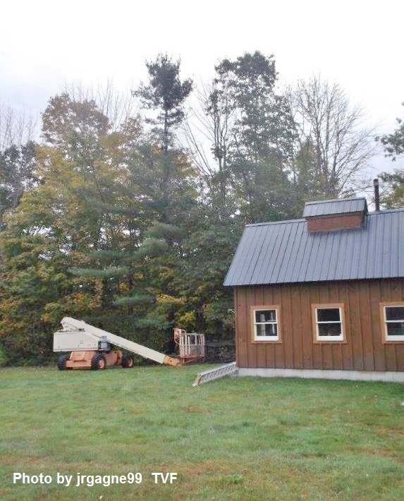
Here are a few pictures. In the second photo, the branches look closer than they actually are. They are a good 15 or 20 feet away. I may do a bit more trimming before returning the man-lift, but it seems pretty clear when I'm actually up there.

 DSCF6977.jpg
DSCF6980.jpg
DSCF6977.jpg
DSCF6980.jpg
Last edited by jrgagne99; 6-Oct-2017 at 3:29 PM.
|
|
|
|
|
6-Oct-2017, 6:53 PM
|
#91
|
|
Retired A/V Tech
Join Date: Aug 2012
Location: S.E. VA
Posts: 2,747
|
Thanks for the photos. That lift looks ideal for the job.
Where is that building as related to the house, or is it part of the house?

|
|
|
|
|
9-Oct-2017, 12:37 PM
|
#92
|
|
Senior Member
Join Date: Sep 2016
Posts: 244
|
Quote:
Originally Posted by rabbit73
Where is that building as related to the house, or is it part of the house?
|
That is my maple sugarhouse, which is part of my barn. The house is located about 100 feet off the left edge of the photo (130 feet between house and tree).
I buried the coax about 18" deep in a 1" black water-pipe and grounded the mast and coax this weekend. I was only able to get about 4-feet deep with the grounding rod, hopefully that is enough.
Question: Does it matter where the grounding block is located, with respect to my Kitz-tech KT-200 pre-amp (upstream or downstream from it). I currently have the grounding block downstream from the pre-amp, since that would be the prototypical configuration if the pre-amp were mast-mounted. But since my pre-amp is at the base of the tree, I appear to have a choice...
|
|
|
|
|
9-Oct-2017, 2:57 PM
|
#93
|
|
Senior Member
Join Date: Sep 2016
Posts: 244
|
I did a bit of research on the mast and coax grounding.
Mast grounding: As I understand it, the main purpose is to prevent static charge build-up at the antenna, thereby reducing the likelihood of a lightning strike. Connection to any decent ground-stake should suffice for this.
Coax shield-grounding: This should be tied to the same ground that the house and its appliances (e.g. my TV) use. Anything else could result in a floating ground or a ground loop.
Therefore, I think I should move my grounding block to the house-side so that I can utilize the house ground-stake, rather than my ground-stake at the tree. Since the entry point of my coax into the house is on the opposite side of the house from my house ground-stake, would it be ok to just connect the grounding-block to the ground-wire (bare wire) of a convenient 110V outlet, such as the outlet that I'm using to power the preamp's power-inserter?
Last edited by jrgagne99; 9-Oct-2017 at 3:02 PM.
|
|
|
|
|
9-Oct-2017, 3:33 PM
|
#94
|
|
Retired A/V Tech
Join Date: Aug 2012
Location: S.E. VA
Posts: 2,747
|
Quote:
|
That is my maple sugarhouse, which is part of my barn. The house is located about 100 feet off the left edge of the photo (130 feet between house and tree).
|
Thank you. I couldn't figure out where the antenna was located when looking at the satellite view.
Quote:
|
Question: Does it matter where the grounding block is located, with respect to my Kitz-tech KT-200 pre-amp (upstream or downstream from it). I currently have the grounding block downstream from the pre-amp, since that would be the prototypical configuration if the pre-amp were mast-mounted. But since my pre-amp is at the base of the tree, I appear to have a choice...
|
You are in a gray area as far as the NEC is concerned. I would treat it like a ham antenna on a tower.
Antenna System Grounding Requirements
http://www.reeve.com/Documents/Artic...ents_Reeve.pdf
A strict interpretation requires a 6 gauge copper conductor between the ground rod at the base of the tree and the house electrical system ground. That would be inconvenient and expensive.
Most hams ground the antenna and the coax at the base of the tower, and ground the coax again at the house to the house electrical system ground. The coax shield then acts as a bond between the two grounds instead of the 6 gauge copper wire.
This is also the method used by many satellite installers. The dish and coax are grounded at the base of a ground mounted dish, and the coax shield is again grounded at the house to the house electrical system ground. The coax used is quad shield that has a lower resistance for a more effective grounding bond. Other dish installers use coax with a 17 gauge copper coated steel messenger wire for grounding the dish, but it is not grounded at the dish.
http://www.dbsinstall.com/diy/Grounding-2.asp
see other parts at that site
Todd Humphrey doesn't speak for the NFPA that publishes the NEC code, but he has some ideas that are helpful. The local electrical inspector (AHJ, authority having jurisdiction) has the final say if you are willing to get him involved. Some inspectors are more friendly than others; a local electrician could tell you.
You get to decide what method to use.
Last edited by rabbit73; 9-Oct-2017 at 3:44 PM.
|
|
|
|
|
9-Oct-2017, 5:33 PM
|
#95
|
|
Senior Member
Join Date: Sep 2016
Posts: 244
|
Quote:
Originally Posted by rabbit73
I couldn't figure out where the antenna was located when looking at the satellite view.
|
The google satellite view is about 4 years old. I built the barn/sugarhouse 3 years ago.
Quote:
Originally Posted by rabbit73
You are in a gray area as far as the NEC is concerned. I would treat it like a ham antenna on a tower.... You get to decide what method to use.
|
Thanks for the suggestions. I think I will ground the coax shield in both places (tree and house).
|
|
|
|
|
9-Oct-2017, 7:35 PM
|
#96
|
|
Senior Member
Join Date: Sep 2016
Posts: 244
|
Quote:
Originally Posted by ADTech
Mount the preamp down closer to the base of the tree so you can reach it if needed. The small sacrifice of noise figure is worth it. Same goes for tall towers. That was a lesson learned the hard way.
|
Thinking about ADTech's recommendation some more, I think I'm going to move my UVSJ from the top of the tree to the bottom of the tree, and use separate down-leads for UHF and VHF. I already have two downleads installed anyway: the original RG-6 downlead and my current RG-11. Extending this line of thought, I think my VHF signal is strong enough that I can get away without amplifying it, and only amplify my UHF feedline. Moving the UVSJ downstream of the amplifier could save me the insertion loss on the UHF side. Does that make sense?
Does the Antennas Direct UVSJ pass power on the UHF side? If not, is there a make/model that does?
Last edited by jrgagne99; 9-Oct-2017 at 7:38 PM.
|
|
|
|
|
9-Oct-2017, 10:50 PM
|
#97
|
|
Antennas Direct Tech Supp
Join Date: Jan 2010
Posts: 2,942
|
Quote:
|
Does the Antennas Direct UVSJ pass power on the UHF side?
|
Yes, it does. 
|
|
|
|
|
17-Oct-2017, 5:22 PM
|
#98
|
|
Senior Member
Join Date: Sep 2016
Posts: 244
|
Since it's been pretty quite on the forum lately, I guess I'll report on the two amplification configurations I have tried recently.
Configuration #1: Amplify UHF-only upstream of UVSJ, by utilizing the UHF-power-pass capability of the Antennas Direct UVSJ (VHF stays unamplified)
Configuration #2: Amplify UHF+VHF downstream of Antennas Direct UVSJ
Configuration #1 gave me about a 1 dB stronger signal on WFFF (my weakest UHF station). But it came at the cost of about 7 dB on the VHF channel WVNY, which I had to leave unamplified for that configuration. Even though WVNY shows an SNR of 21 dB at the TV for configuration #1 (15 dB required for reception), I decided to use configuration #2 for now. Either one seems equivalent in terms of reception, and both provide about 6 dB more than the minimum needed for reliable reception of the weakest channel...
Current overall setup:
Antennas: DB8e and MCM-30-2476 at about 55-ft AGL in a pine tree. The DB8e uses 50-ft of RG-11 to base of tree, the MCM-30-2476 uses 50-ft of RG-6. Signals combined at base of tree using Antennas Direct UVSJ, then Kitztech KT-200 preamp, then 150-feet of direct-burial-grade RG-6 to house (in underground conduit, belt+suspenders), then KT power inserter, then 30-ft of RG-6 to TV.
My current actual reception report:
WVNY, Real 13, (TVFool NM=6.6 dB): SNR at TV= 29 dB
WPTZ, Real 14, (TVFool NM=9.2 dB): SNR at TV= 29 dB
WCAX, Real 22, (TVFool NM=8.2 dB): SNR at TV= 29 dB
WETK, Real 32, (TVFool NM=-2.2 dB): SNR at TV= 26 dB
WFFF, Real 43, (TVFool NM=-5.8 dB): SNR at TV= 22 dB
Just out of curiosity, does anyone know if there is a UVSJ that passes power on both ports? If so, does anyone know of a pre-amp system that can power two pre-amps using just one power inserter?
Last edited by jrgagne99; 17-Oct-2017 at 5:48 PM.
|
|
|
|
|
17-Oct-2017, 6:14 PM
|
#99
|
|
Antennas Direct Tech Supp
Join Date: Jan 2010
Posts: 2,942
|
Quote:
|
Just out of curiosity, does anyone know if there is a UVSJ that passes power on both ports?
|
No, but it wouldn't be hard to modify ours so it would do so. It would involve opening it up and soldering a coil between the VHF in and the common port terminals, just like the internal UHF filter is bypassed.
You can also use two SAT/TV diplexers in a back-to-back configuration to bypass a non-power-passing component.
Quote:
|
If so, does anyone know of a pre-amp system that can power two pre-amps using just one power inserter?
|
I have both a distribution amp in my attic and a preamp out on the mast running from a single power inserter in my living room. I'd have to go up in the attic and review how I did it, I just threw it together out of what I had in the "junk box" and it probably wouldn't be the "optimized" solution.
|
|
|
|
|
19-Mar-2018, 8:55 PM
|
#100
|
|
Senior Member
Join Date: Sep 2016
Posts: 244
|
Channel Sharing
I have noticed that after the re-pack, WNNE real-25 from Mount Ascutney (which I believe is a local translator for WPTZ on real-14 from Mount Mansfield) will be entering a channel sharing agreement with WPTZ. On rabbitears.info, this shows as 25 --> Sh. 14 for WNNE.
What exactly does this mean? My guess is that the ch-25 signal from Mount Ascutney will cease, and that the periodically-displayed station-ID overlay for WPTZ will now say WPTZ and WNNE, instead of just WPTZ. Is that right? It doesn't mean that the tower that was broadcasting 25 on Mount Ascutney will switch to 14, which would be big co-channel interference problem, right?
What is the short summary of the reasons behind these so-called channel sharing agreements?
|
|
|
|
 Posting Rules
|
You may not post new threads
You may not post replies
You may not post attachments
You may not edit your posts
HTML code is Off
|
|
|
|
|


