 |
 15-Jul-2016, 8:57 PM
|
#1
|
|
Junior Member
Join Date: Jun 2016
Location: Boulder, Colorado
Posts: 17
|
Boulder Reception #2: Spectral Analysis
I have been struggling with reception in the Foothills outside Boulder, CO (elevation 6700ft) and this has been discussed elsewhere ( http://forum.tvfool.com/showthread.php?t=16002) where there is a TVFool Report and considerable discussion. Many thanks to all who contributed in particular Rabbit73.
The bottom line is that I sometimes could get an adequate signal level and quality for High VHF channels 7 & 9 using either a high gain UHF or VHF antenna. It seemed to make no difference. The UHF actually seemed better than the VHF. In either case, pointing directly at the source (160 deg Magnetic) yielded no usable signal, while pointing at ~90-100 degrees often worked well.
The criteria for "usable" here is a high symbol quality (as well as strength) for a SiliconDust HDHR networked tuner. Symbol quality is the number 1 factor that determines if a recording will be watchable, or even occur.
I decided to take things to the "next level" and put together a "poor man's" Spectum Analyzer usung an RTL-SDR (software defined radio) and software from Ear-to ear Oak ( http://eartoearoak.com/software/rtlsdr-scanner). This roughly $20 Spectrum Analyzer works surprisingly well but ain't no $3000 Textronix replacement.
The bottom line is that signal levels are very good with both the VHF and UHF antennas even for channels 7 & 9 for the 8-bay UHF antenna. I do not see a lot of noise overlapping the bands in which the digital data is being transmitted either. I'm forced to believe that the reception problem is some multipath-like effect where the digital data is arriving at slightly different times leading to errors and low symbol rates. The surrounding hillsides and atmospheric reflections may be the problem (it has become cloudy here and the symbol rate has gone up to 100%!) Moreover the signal levels are always pretty high, even when the symbol rate is zero! Usually the signal level is 15-30 dB above the noise floor.
Unfortunately the spectrum analyzer cannot resolve the region of the digital data very well (as far as I can tell), so I don't see how to pursue this further. If any of you have experience in this I'd love to know. So attached are screen shots of the spectral region that includes channels 7 & 9. One was for good symbol quality, the other," TWO..." low.
|

|

|
|
16-Jul-2016, 6:52 PM
|
#2
|
|
Retired A/V Tech
Join Date: Aug 2012
Location: S.E. VA
Posts: 2,747
|
Thanks for the interesting screen shots and your well-written report.
It looks like you have done well putting together the SDR.
Quote:
|
In either case, pointing directly at the source (160 deg Magnetic) yielded no usable signal, while pointing at ~90-100 degrees often worked well.
|
I think you are receiving a signal reflected off the hill that is east of your location. Here is a view looking ~SSE toward 7 & 9:

Quote:
|
The criteria for "usable" here is a high symbol quality (as well as strength) for a SiliconDust HDHR networked tuner. Symbol quality is the number 1 factor that determines if a recording will be watchable, or even occur.
|
Yes, exactly correct. The symbol quality is the inverse of uncorrected errors; 100% symbol quality = zero uncorrected errors. The FEC (forward error correction) has a limited ability to correct errors. Once that limit is exceeded, the signal can not be decoded.
Quote:
|
I do not see a lot of noise overlapping the bands in which the digital data is being transmitted either.
|
The OTA digital TV signal is an analog (AM 8VSB, 8-level vestigial sideband amplitude modulation) signal that carries the digital information.
Quote:
|
I'm forced to believe that the reception problem is some multipath-like effect where the digital data is arriving at slightly different times leading to errors and low symbol rates.
|
I agree, that seems most likely. Multiple reflections of the signal are arriving at your antenna from different directions and at different times. The greater the time difference between the primary signal and a reflection (echo), the more difficult it is for the tuner to resolve.

Special test equipment is needed to display the echoes.

The antenna worked better inside because it didn't have to deal with as many reflections, and a UHF antenna worked well because some of the reflections were attenuated.
Quote:
|
atmospheric reflections may be the problem (it has become cloudy here and the symbol rate has gone up to 100%!
|
If a temperature inversion forms between the transmitter and your location, the signal can become trapped in an upper layer, unable to bend down to your location by refraction. When the temperature falls, the signal is no longer trapped.
http://www.mike-willis.com/Tutorial/PF6.htm
scroll half way down to Example of a path profile diagram
http://www.dxfm.com/content/propagation.htm
scroll down to An illustration of a high-altitude tropospheric duct.
Last edited by rabbit73; 16-Jul-2016 at 7:55 PM.
|
|
|
|
|
16-Jul-2016, 7:40 PM
|
#3
|
|
Retired A/V Tech
Join Date: Aug 2012
Location: S.E. VA
Posts: 2,747
|
Quote:
|
Unfortunately the spectrum analyzer cannot resolve the region of the digital data very well (as far as I can tell), so I don't see how to pursue this further.
|
The SA display does show amplitude vs frequency. The pilot carrier at the low end doesn't seem very prominent in your display as it is in the displays by Chris and Pete. A good pilot carrier is needed for tuner lock.
You and Chris have your noise floor at -50, but Pete has moved his window down to see weaker signals.
RTL2832U + R820T DVB-T USB Tuner Card Hints & Kinks
Adjusting where the Noise Floor displays
http://www.highdefforum.com/1353614-post9.html
It is possible to have a good looking flat display of the channel on the SA without being able to receive the signal. A flat display implies no multipath, but multipath reflections can fill in the dips, as Trip in Va found out when he was living in Chattanooga:
Chattanooga: Trouble getting OTA Signal
http://www.avsforum.com/forum/25-hdt...l#post22156611 Post 25
http://www.avsforum.com/forum/25-hdt...l#post22172949 Post 26
My post 26 above gives a quote by Dr. Bendov, et al, that explains why the display can be misleading about multipath and implied SNR.
The only way Trip could receive the locals was to put an antenna in a trash can:
http://www.avsforum.com/forum/25-hdt...l#post21358820

It worked because it narrowed the acceptance angle to reject reflections.
another example:
Bill Naivar's Anti-ghosting Antennas Revisited
http://forum.tvfool.com/showpost.php...27&postcount=7


Last edited by rabbit73; 16-Jul-2016 at 10:39 PM.
|
|
|
|
|
16-Jul-2016, 9:38 PM
|
#4
|
|
Junior Member
Join Date: Jun 2016
Location: Boulder, Colorado
Posts: 17
|
Thank you!!!
Rabbit73:
Thank you for the wonderful analysis and point-by point reply. I will spend quite some time looking into these and absorbing the information.
Today the weather has been such that the Symbol Quality has been quite good and both the VHF and UHF antennas work. It's cloudy. The VHF antenna has a good 10 dB gain over the UHF for channels 7 & 9, but that does not seem to matter of course because of the multipath effects.
At one point during the day CH7 had a 100% Symbol Quality at the same time, adjacent CH9 was zero. I did a spectral scan. I've attached the figure. I may be going overboard here but it looks as if the "hash" for Channel 9 is really a band while CH7 seems to be narrower in the width of the hash. Perhaps I'm reading too much into the difference.
Anyway I had been thinking along the line you suggested by putting the antenna in a trash can. I was thinking of getting some fairly open wire mesh and wrapping it around either the VHF or UHF antennas to see if that helps.
BTW I get a measurable signal with a simple dipole and was thinking of putting an amp on it and shielding it to reduce signals coming in from the side.
Thanks again for the great information!
Last edited by acat; 16-Jul-2016 at 9:40 PM.
|
|
|
|
|
16-Jul-2016, 11:13 PM
|
#5
|
|
Retired A/V Tech
Join Date: Aug 2012
Location: S.E. VA
Posts: 2,747
|
Your report repeated for reference:
http://www.tvfool.com/?option=com_wr...e2cbfa5f7ed489
Quote:
|
At one point during the day CH7 had a 100% Symbol Quality at the same time, adjacent CH9 was zero. I did a spectral scan.
|
Thanks for the new scan. They both LOOK pretty healthy. CH 9 is almost as strong as 7, but 9 has a tilt in the channel level and its pilot carrier isn't as well defined.

The only differences I can find are 9 is running a little less power, its antenna is a little lower, and it is on a higher frequency which will change the scattering of its signal from the rough terrain.
But, the tuner makes the final decision on signal quality (SNR & errors), and it says NO GO for 9.
Last edited by rabbit73; 17-Jul-2016 at 12:20 AM.
|
|
|
|
|
18-Jul-2016, 2:42 PM
|
#6
|
|
Retired A/V Tech
Join Date: Aug 2012
Location: S.E. VA
Posts: 2,747
|
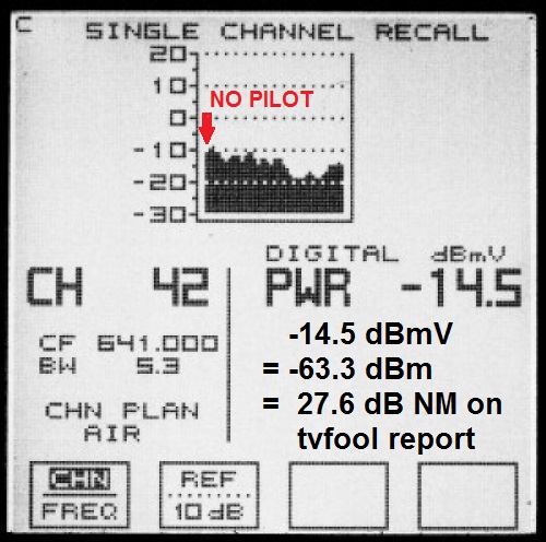
In theory, it should be possible to optimize the antenna aim for channel 9 by monitoring its pilot carrier, which is at 186.31 MHz.

Quote:
It is not possible to receive digital TV audio with a scanner or AM/FM receiver.
Before the transition from analog to digital TV in 2009, audio from analog TV stations could be received in wideband FM (WFM) mode. Each audio channel used 100 kHz bandwidth.
The 8-VSB modulation used in ATSC (DTV) has a pilot carrier that serves as a reference frequency for DTV receivers and can be heard on an AM or FM (narrow band) receiver. The pilot carrier is approximately 310 kHz (.31 MHz) above the lower band edge. The exact frequency used may vary because the transmitted signal may be offset slightly to reduce interference.
|
http://wiki.radioreference.com/index...on_Frequencies
Last edited by rabbit73; 18-Jul-2016 at 2:57 PM.
|
|
|
|
|
18-Jul-2016, 2:53 PM
|
#7
|
|
Antennas Direct Tech Supp
Join Date: Jan 2010
Posts: 2,942
|
Quote:
Originally Posted by rabbit73

In theory, it should be possible to optimize the antenna aim for channel 9 by monitoring its pilot carrier, which is at 186.31 MHz.
|
In actual practice, it's quite possible to have a perfect pilot bu have another part of the 5.38 MHz bandwidth completely grunged out due to multipath condition. That would show up as a deep notch, for example, somewhere within that bandwidth.
|
|
|
|
|
18-Jul-2016, 3:15 PM
|
#8
|
|
Retired A/V Tech
Join Date: Aug 2012
Location: S.E. VA
Posts: 2,747
|
Quote:
|
In actual practice, it's quite possible to have a perfect pilot bu have another part of the 5.38 MHz bandwidth completely grunged out due to multipath condition. That would show up as a deep notch, for example, somewhere within that bandwidth.
|
That is correct, but his scan doesn't have a notch, so I think it is worth a try. OP acat is at the point now where he is willing and able to try any experiment to receive channel 9, witness the fact that he climbed the RTL-SDR learning curve with great success. He is even willing to try an Anti-Ghosting Antenna. 
I have no desire to discourage a true antenna experimenter; I often learn from them.
And, just to make it more confusing, according to Dr. Bendov, you can have a flat scan without a notch, but the signal doesn't decode because the reflections have filled in the notch.
DTV Coverage and Service Prediction, Measurement and Performance Indices by Dr. O. Bendov, et al.
page 4
VIII. SNR AND “FIELD STRENGTH” MEASUREMENT VIA
SPECTRUM INTEGRATION
Quote:
Defining the Signal as the total received power and the Noise as AWGN (Additive White Gaussian Noise) leads to the conclusion that the SNR at the input to the receiver increases with increased multipath.
In urban and indoor situations, there may not even be a main signal, only reflections, some of which are of equal magnitude.
If all multipath signals are part of the signal power, then the SNR margin may not be an indicative figure of merit of reception robustness. In any case, even accurate measurement of the total received power may not be trivial.
The integrated signal power is not just the Desired Signal power. It includes, Man-made, Galactic, and thermal noises and residual transmitter generated in-band noise. It also includes some but not necessarily all multipath signals. For example, pairs of identical and asymmetric echoes, one of positive amplitude and positive delay relative to the main signal and one of negative amplitude and negative delay relative to the main signal, will cause only a second-order distortion of the displayed power spectrum. They will create group delay. Thus, in a multipath channel, a pair of such echoes would measure high SNR when using the spectrum integration technique whereas in reality, the true SNR would be much lower.
There may be other combinations of echoes that would yield essentially flat spectrum display.
|
I still think it's worth a try because it worked with my Salelco DisplayMax 800 single channel scan.
Here is a signal that is strong enough, but doesn't decode because there is no direct signal, only reflections.
When the antenna was aimed at the transmitter, the signal was received:

Last edited by rabbit73; 18-Jul-2016 at 6:31 PM.
|
|
|
|
|
18-Jul-2016, 4:20 PM
|
#9
|
|
Antennas Direct Tech Supp
Join Date: Jan 2010
Posts: 2,942
|
Yep, I certainly agree with all that. Even with a spectrum analyzer, reception results can still exhibit anomalies. As always, YMMV...
|
|
|
|
|
18-Jul-2016, 9:53 PM
|
#10
|
|
Retired A/V Tech
Join Date: Aug 2012
Location: S.E. VA
Posts: 2,747
|
Thank you.
As I said to Calaveras on AVS, I might be WRONG, but my comment IS relevant.
I think it is up to the poster with the reception problem to decide if my idea has any merit.
|
|
|
|
|
18-Jul-2016, 9:58 PM
|
#11
|
|
Junior Member
Join Date: Jun 2016
Location: Boulder, Colorado
Posts: 17
|
Back of the Envelope Calculations & Some Tentative Results
Thanks Rabbit73 & AdTech for the thoughtful insights & suggestions.
So some rough calculations...
Pinebrook Hills, a possible source of reflections is roughly 1 mile distant. At the speed of light that amounts to a ~5 microsecond delay. However, 1 cycle at 180 Mhz is 0.00555 microsec, and since the reflection delay is likely smeared over a range of times given that the reflecting surface is pretty ugly, interference with the digital signal seems to be a given. (if I had done this calculation first, I might not have started!)
This is just a tentative result, since the reliability of any solution so far has been poor...but... I did put a screen up to the side of the VHF antenna with the SiliconDust Receiver software running on channel 7 next to me on a laptop. Without the wire mesh, the symbol rate was Zero. With the wire mesh it went to 100%. I added and removed it several times and it SEEMED reproducible, but I am reluctant to bet the farm on it.
I'll need to give some thought to a more permanent construction for the shield as we have notoriously high winds in the mountains. I don't want the antenna to blow all the way to Kansas. I suppose some aluminum rods widely spaced as they are at the back of the 8-bay UHF and VHF antenna would be a good start along with some plastic pipe as a support.
|
|
|
|
|
18-Jul-2016, 10:32 PM
|
#12
|
|
Retired A/V Tech
Join Date: Aug 2012
Location: S.E. VA
Posts: 2,747
|
Thanks for the interesting report.
Quote:
|
Without the wire mesh, the symbol rate was Zero. With the wire mesh it went to 100%.
|
WOW! Very impressive test; sounds promising.
Which way was the antenna aimed, and which side of the antenna for the mesh?
I'm trying to figure out if you were using a signal coming over the mountain from SSE or a signal from the east for reception.
I'm wondering how close the mesh can be to the antenna without detuning it.
Quote:
|
I don't want the antenna to blow all the way to Kansas.
|
Ha Ha! Yes, you don't want to convert it into a kite.
Sounds like a compromise. Closer spacing of the rods or wires is more effective, but it increases the wind load.
Last edited by rabbit73; 21-Jul-2016 at 1:31 PM.
|
|
|
|
|
18-Jul-2016, 11:14 PM
|
#13
|
|
Junior Member
Join Date: Jun 2016
Location: Boulder, Colorado
Posts: 17
|
Antenna Orientation
I used the VHF antenna and pointed it at Pinebrook Hill. I then placed the mesh to the left of the antenna as seen from behind. The "reasoning" was as follows. I seem to get the best signal from approximately ESE, roughly where the hill is. However we have hills on either side, North and South. The one to the North is quite close, less than a mile I guess, whereas the one to the south is more distant and in the direction of the broadcast tower. It was also just easier to do
|
|
|
|
|
20-Jul-2016, 6:47 PM
|
#14
|
|
Junior Member
Join Date: Oct 2013
Posts: 27
|
Wow, Rabbit73's brilliant
Quote:
Originally Posted by rabbit73
The SA display does show amplitude vs frequency. The pilot carrier at the low end doesn't seem very prominent in your display as it is in the displays by Chris and Pete. A good pilot carrier is needed for tuner lock.
You and Chris have your noise floor at -50, but Pete has moved his window down to see weaker signals.
RTL2832U + R820T DVB-T USB Tuner Card Hints & Kinks
Adjusting where the Noise Floor displays
http://www.highdefforum.com/1353614-post9.html
It is possible to have a good looking flat display of the channel on the SA without being able to receive the signal. A flat display implies no multipath, but multipath reflections can fill in the dips, as Trip in Va found out when he was living in Chattanooga:
Chattanooga: Trouble getting OTA Signal
http://www.avsforum.com/forum/25-hdt...l#post22156611 Post 25
http://www.avsforum.com/forum/25-hdt...l#post22172949 Post 26
My post 26 above gives a quote by Dr. Bendov, et al, that explains why the display can be misleading about multipath and implied SNR.
The only way Trip could receive the locals was to put an antenna in a trash can:
http://www.avsforum.com/forum/25-hdt...l#post21358820
It worked because it narrowed the acceptance angle to reject reflections.
another example:
Bill Naivar's Anti-ghosting Antennas Revisited
http://forum.tvfool.com/showpost.php...27&postcount=7
|
The Megalithia site, is that yours?? Brilliant. I just got lost in it and damned myself for losing all of my morning free time by reading it.
PS also a fan of Lord Kelvin. Great stuff. I'm impressed. I'm saving your website to my bookmarks (for the readers, it's the hyperlink at the bottom of rabbit73's posts) I wish I had your electrical know-how!! I was a dork of a child- taking apart old radios and fiddling with the insides, turning the "pots" so I could receive aircraft radio transmissions (for what it's worth, i had no idea this was a 'thing' nor had anyone told me of the possibility, i was just an extremely curious child) electricity, radio, and telephone science has fascinated me since childhood. If you guessed I was not a popular child in public school you guessed correctly. PPS I also had the thick glasses and once my father had to glue and tape the middle together when they broke, which was often, because the glass was SO thick, and the bridge over the nose so thin, it could not handle the weight of the lenses. It was not until 13 years of age I was allowed contact lenses, but by then my psyche had already been permanently crushed by years of mockery. Such is life!
Thanks Rabbit73- do you have any recommendations of links to websites with fun stuff to read similar to yours? even simple ones are fine- I am always on the lookout for more- thanks - apologies to the OP I do not mean to circumvent your post on reception- just piping in a bit ok?
|
|
|
|
|
21-Jul-2016, 7:01 PM
|
#15
|
|
Retired A/V Tech
Join Date: Aug 2012
Location: S.E. VA
Posts: 2,747
|
analogqueen:
Thank you for your kind words. Sometimes I can help a poster with a reception problem; sometimes not.
The Megalithia site is not mine, but I like it a lot because making antenna measurements is one of my favorite things to do. The site is in the UK and talks about DTT (Digital Terrestrial Television) which is equivalent to our OTA in the US. I put the link in my signature because it describes an inexpensive method of testing reception than might be helpful. It uses an attenuator to find out how much margin to dropout you have.
I too became fascinated with electronics at an early age. When I was 8 years old my father helped me build a crystal set radio using my bedspring as an antenna, and I often fell asleep with my headphones on listening to WOR. I became an amateur radio ham in the early 1950s, which allowed me to do many antenna experiments. I'm now 83 and still fascinated by antennas.
In high school I was the school photographer which helped me to interact with my classmates socially. My glasses also broke at the bridge. I drilled a hole in each half, ran a wire through, twisted the wire tight at the front, and covered it with adhesive tape. A genuine nerd repair that was secure until I could get new frames.
Both hobbies prepared me for the jobs I later held in my life.
I started out to be an EE at Rutgers, but when my father died I had to leave school and got drafted. I served in the Army as a radio operator and then was a civilian AV tech (photography and electronics) for the government for 30 years.
If you don't already know about it, the hdtvprimer.com website created by Ken Nist, MSEE (ret), KQ6QV, might be helpful; an example:
http://www.hdtvprimer.com/antennas/siting.html
home page
http://www.hdtvprimer.com/
Here is a FAQ thread on the Canadian forum:
http://www.digitalhome.ca/forum/81-o...edge-base.html
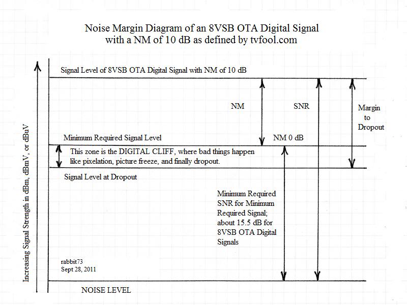
Andy Lee, who created this tvfool website, drew two diagrams that show what happens to a TV signal on its way from the transmitter to the TV. I added a few notes to his excellent diagrams:


Here are my diagrams that show two ways to visualize what happens between -91 dBm and the Thermal Noise Floor at -106 dBm:


Do you have any specific topic in mind?
Very OK; no harm done. I'm glad that I was able to give acat a few ideas to try, and enjoyed reading your story.
Best regards,
rabbit
W4...
ex-W2...
ex-DL4..
Last edited by rabbit73; 21-Jul-2016 at 7:56 PM.
|
|
|
|
|
21-Jul-2016, 8:45 PM
|
#16
|
|
Junior Member
Join Date: Oct 2013
Posts: 27
|
Thanks Rabbit73!
Thanks for the links- apologies to the original poster's query, I hope I haven't waylaid the topic!
RAbbit73 your anecdotes are interesting, I love to read things like that. What a wonderful father to teach you crystal radio set building at that age. In the US today children's "babyhood" is extended far beyond what is beneficial, unfortunately. This is off of an old German method, and part of another initiative set forth by our govt - uh oh another tangent meant for another forum, let's just leave it that it makes me very angry denying youth the benefit of increased learning and knowledge.
Did I mention that I am a girl- er, "woman" rather- I should have mentioned that in mine own anecdote, especially the part about the thick glasses and nerd repair, ugh being a girl we were subject to a much stricter aesthetic example than the boys. I Laughed out loud at your spectacles repair job! I think my father attempted a similar repair and it did not work then, the wire wouldn't keep the frame together (guhh.. in school having your big glasses crumble off of your face in gym class- mortifying)
Thank you for your links, and the info on them. Very interesting to me. I wonder if N America will ever implement DTT? (no need to answer, just an out loud wonder)
HDTV Primer I have in my bookmarks already but its been a while visiting, I'll got check it out again-
Regarding a "specific topic in mind" - nothing specialized, I like it all. Even modifying electronics, anything. I have most of the popular amateur radio/HF radio/antenna, dxing, tv forums and all related in a huge list of bookmarks.
I am a member of radioreference.com under "fleef"
eham I am "flyerkite" or something I can't recall it now, but it is a vanity non-ham sign.
I am an avid HF listener, I have a 2meter transceiver and many radios of all sorts including satellite hobby, but actually transmitting and DXing for contacts never interested me, so I never got licensed- yet!
Obviously this TVFool forum attracts our sort of people, as curiosity for solving problems related to antennas and theory, electronics, well it's natural.
Enjoy reading your replies to queries, it is quite remarkable how you take time out to respond in such detailed and careful solutions and possible scenarios.
thanks Rabbit73 nice "chatting" with you
|
|
|
|
 Posting Rules
|
You may not post new threads
You may not post replies
You may not post attachments
You may not edit your posts
HTML code is Off
|
|
|
|
|


