 |
|
 23-Jul-2016, 10:44 PM
|
#1
|
|
Retired A/V Tech
Join Date: Aug 2012
Location: S.E. VA
Posts: 2,747
|
Tilt Feature of MCM Stellar Labs 30-2475 & 30-2476
Quote:
|
Originally Posted by Nascarken
Good day rabbit 73 the stellar Labs,high VHF outdoor TV antennas,on both antennas have the tilt Feature on them, #30-2475&76,just like the antennas Direct 91XG,well have a good day and 73,
|
Thank you for the information, but I don't see that in the description of the antenna, in the instructions, or in the image. Where do I find that?
 http://www.mcmelectronics.com/produc...-2476-/30-2476
Last edited by rabbit73; 24-Jul-2016 at 12:59 AM.
|

|

|
|
23-Jul-2016, 11:18 PM
|
#2
|
|
Retired A/V Tech
Join Date: Aug 2012
Location: S.E. VA
Posts: 2,747
|
Quote:
|
Originally Posted by Nascarken
 how do I take a picture of the antennas so I can show you the boxes and the clamp and the whole thing and if you order one you will see but I don't lie I have a Kindle I paid can you give me some info on how to send a picture of them all 4 antennas,have it &call m c m electronics and ask them to,because I have 4 of them,#18005434330, |
Quote:
|
Originally Posted by Nascarken
Yes Rabbit 73 I looked at the same picturers you are showing,be for I bought them to but when I opened the box and looked at it I couldn't believe. My eyes with the title feature,on THEM,I think you should buy one and see for yourself, one more + FOR that STELLAR LABS high gain VHF outdoor TV ANTENNA,#30-2475& ''''''''''+the#30-2476,I wouldn't lie about it Rabbit and can you tell me how to get a picture of this subject to you,I have a Kindle and I don't no HOW to make it work,well thanks again and have a good day 73  |
Ken
I will put this on the open forum where it belongs and you can add the photo as an attachment.
You need an image host to put a photo in a PM.
Can you show us a photo of how you actually do it with YOUR antenna?
Stellar Labs 30-2476 extended
https://freetvforme.wordpress.com/20...-labs-30-2476/
rabbit
Last edited by rabbit73; 23-Jul-2016 at 11:50 PM.
|
|
|
|
|
24-Jul-2016, 12:24 AM
|
#3
|
|
Retired A/V Tech
Join Date: Aug 2012
Location: S.E. VA
Posts: 2,747
|
By Donnie on June 18, 2016
Quote:
|
I was about to give this a 4 star review because it came with the last section twisted. Me being the impatient person I am straightened it out with a vise and some adjustables. Although it caused some cosmetic damage (can't see the dents from the ground) it picks up great. Asides from coming with a twist this thing is built really well for a 43 dollar antenna, for an antenna of any price range, and the mount it comes with allows you to aim the antenna up which in my case dramatically increased signal strength (at least 10%). I can get channel 13 which is 72.9 miles from me at 70% if I want but I have it combined with other antennas and had to adjust it to get in an)other station, still getting 60-65%. If there is a high band VHF station you are sort of picking up with a smaller/uhf antenna I would definitely try this antenna.
|
https://www.amazon.com/Deep-Fringe-D.../dp/B01BP4KV9Y
|
|
|
|
|
26-Jul-2016, 11:51 AM
|
#4
|
|
Antenna Enthusiast
Join Date: Mar 2016
Location: Beach Park IL
Posts: 318
|
30-2476 adjustable clamp
Rabbit,
I'll try to get a better pic, this one doesn't show the incremental adjustment holes, but shows the curvature at the top:
2016-7-25 West array (5)resize.jpg
http://forum.tvfool.com/attachment.p...1&d=1469533592
Sorry to say, I can't get the pics to show here in this forum. I used the technique as in Hi Def, doesn't seem to work.
Last edited by bobsgarage; 28-Jul-2016 at 11:29 AM.
|
|
|
|
|
26-Jul-2016, 2:50 PM
|
#5
|
|
Retired A/V Tech
Join Date: Aug 2012
Location: S.E. VA
Posts: 2,747
|
Thanks for the photo, Bob. It works here too. You put the forward slash after the G instead of before the I.
I edited your photo

I see how it clamps around the boom, but I don't understand yet how the angle can be adjusted.
Are the adjustment holes under the clamping plate or in it? How many degrees between each setting?
Do you need to move two bolts, or just rotate the plate with the bottom bolt as a pivot?
Last edited by rabbit73; 26-Jul-2016 at 6:25 PM.
|
|
|
|
|
27-Jul-2016, 12:00 PM
|
#6
|
|
Antenna Enthusiast
Join Date: Mar 2016
Location: Beach Park IL
Posts: 318
|
HI Rabbit
OK, got it, the forward slash is before IMG at the end though. ( [/IMG] )
Adjustable Horizontal Angle Clamp.png

OK I admit, I found this pic on the S.S. HDB91X install instructions. Stellar Labs could learn a lot from S.S. instructions.
Anyhow, I believe that Solid Signal and Stellar Labs get their antenna clamps from the same supplier, because I put the two antennas up on the same day and saw no difference in the mast clamps.
|
|
|
|
|
27-Jul-2016, 12:40 PM
|
#7
|
|
Antenna Enthusiast
Join Date: Mar 2016
Location: Beach Park IL
Posts: 318
|
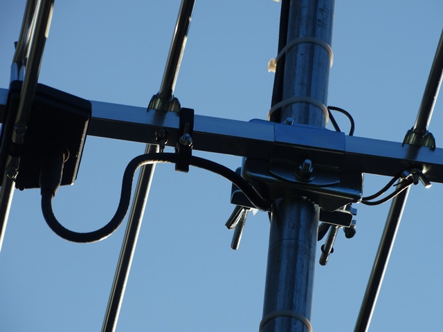
Rabbit,
Here's a little extra effort on the clamp Pics. (I climbed the 10 foot tripod on my east array and zoomed the hi def camera). Kind of a little repayment for all your great help  30-2476:
 HDB91X:

A zoom out to see the effects of a "first hole adjustment", I hope you can see the forward tip up:

|
|
|
|
|
27-Jul-2016, 1:55 PM
|
#8
|
|
Retired A/V Tech
Join Date: Aug 2012
Location: S.E. VA
Posts: 2,747
|
Thanks for the photos, Bob. I appreciate the extra effort that it took. I can see clearly how to make the adjustment.
If the notch sits on the bolt, then the angle doesn't shift.
I see the upward tilt of your antennas, but it looks like the slot isn't long enough to have the boom horizontal with no tilt. Maybe a little tilt is a good idea. It helped with my 4-bay bowtie antenna tests, even when I had a clear LOS path over water from the transmitters.

Last edited by rabbit73; 27-Jul-2016 at 2:21 PM.
|
|
|
|
|
27-Jul-2016, 11:42 PM
|
#9
|
|
Antenna Enthusiast
Join Date: Mar 2016
Location: Beach Park IL
Posts: 318
|
Quote:
Thanks for the photos, Bob. I appreciate the extra effort that it took. I can see clearly how to make the adjustment.
If the notch sits on the bolt, then the angle doesn't shift.
I see the upward tilt of your antennas, but it looks like the slot isn't long enough to have the boom horizontal with no tilt. Maybe a little tilt is a good idea. It helped with my 4-bay bowtie antenna tests, even when I had a clear LOS path over water from the transmitters.
|
Rabbit,
I forgot to mention that I was able to get the antenna level when I first installed it. I think my adjustment is between the first slot and the adjustment limit. In other words, my adjustment isn't locked into an adjustment groove. In the pictures, the flat washer covers the end of the adjustment in both antennas.
Same with the HDB91X. I tilted them a little because of the distant trees.
These two antennas have quite a bit of tilt when adjusted all the way.
What about that car? Looks like someone is serious about checking signals.
Thanks, Bob
|
|
|
|
|
28-Jul-2016, 2:24 PM
|
#10
|
|
Retired A/V Tech
Join Date: Aug 2012
Location: S.E. VA
Posts: 2,747
|
Quote:
|
What about that car? Looks like someone is serious about checking signals.
|
The two antennas on the car is how I compare the gain of two antennas. I use a stable OTA signal and switch rapidly between the two antennas with an A/B switch and record the signal level readings from my Sadelco DisplayMax 5000 Signal Level Meter.
The two antennas are the new Channel Master 4221HD and the original 4221.
The 4221HD wasn't performing as well as expected because of some design faults. There is a modification thread on the DHC forum.
http://www.digitalhome.ca/forum/186-...are-hacks.html
My post
http://www.digitalhome.ca/forum/1167870-post221.html
My chart of test results:

The second attachment is a larger version of the chart, but I like to limit the width of images that show in a post to 800 pixels; anything wider makes the posts too wide.
Last edited by rabbit73; 28-Jul-2016 at 5:44 PM.
|
|
|
|
|
28-Jul-2016, 2:59 PM
|
#11
|
|
Retired A/V Tech
Join Date: Aug 2012
Location: S.E. VA
Posts: 2,747
|
Last edited by rabbit73; 28-Jul-2016 at 3:03 PM.
|
|
|
|
|
28-Jul-2016, 5:30 PM
|
#12
|
|
Retired A/V Tech
Join Date: Aug 2012
Location: S.E. VA
Posts: 2,747
|
The tilt adjustment has 5 notches and 4 peaks between the notches.
The angle between the 2nd and 4th peak is about 20 degrees, which means that the notches are about 10 degrees apart.
The adjustment range for the notches is 0, 10, 20, 30 and 40 degrees.


Last edited by rabbit73; 28-Jul-2016 at 5:33 PM.
|
|
|
|
|
28-Jul-2016, 6:33 PM
|
#13
|
|
Senior Member
Join Date: Jan 2014
Location: Virginia!
Posts: 329
|
LOL. I was just looking at Rabbit's post with the photo of the antenna fixed to the roof of a car (post #8 above). It really gives a good visual image to the old adage "Up against the wall!" 
|
|
|
|
|
28-Jul-2016, 6:59 PM
|
#14
|
|
Retired A/V Tech
Join Date: Aug 2012
Location: S.E. VA
Posts: 2,747
|
Yeah, not much signal coming off the wall.
The wall was used as a background to show the antennas clearly.
You don't really think I did the test with the antennas aimed at the wall, do you?
Looks like I'll need to edit the photo if that is the impression it gives.
I actually used the setup down by the river, which gave a clear LOS path to the towers. The signals were quite stable, which was needed for a decent test, except when a boat passed by, which created dynamic multipath. I hunted for a long time and drove many miles to find a good test site.


TV Fool signal report:
http://www.tvfool.com/?option=com_wr...e2cb2ad8638cf6

Last edited by rabbit73; 29-Jul-2016 at 1:52 AM.
|
|
|
|
|
29-Jul-2016, 2:42 AM
|
#15
|
|
Antenna Enthusiast
Join Date: Mar 2016
Location: Beach Park IL
Posts: 318
|
A challenge for the best
Quote:
Originally Posted by rabbit73

The tilt adjustment has 5 notches and 4 peaks between the notches.
The angle between the 2nd and 4th peak is about 20 degrees, which means that the notches are about 10 degrees apart.
The adjustment range for the notches is 0, 10, 20, 30 and 40 degrees.
|
Hey Rabbit !
Wow! You have "protracted" my interest once again.
You have so many tricks up your sleeve. How'd ya do it? I mean, superimpose the protractor over the photo?
That my friend is very cool and useful.
Your skills still amaze me. Makes me want to say O'S M! ")
Seriously though, 4 degrees, that seems to back up what I was thinking, the adjustment was between notches. I was going to go with the first notch, but the angle seemed to be too extreme. Even 4 degrees seems like a lot.
I am wondering... Do you have any way to show an angle of what 4 degrees (or 5 or 10 or 20 etc...) aimed from my location to Milwaukee or Chicago transmitters would look like? Now that's a challenge!
TV Fool report:
http://www.tvfool.com/?option=com_wr...e2cbeac8b096de
Last edited by bobsgarage; 29-Jul-2016 at 11:57 AM.
|
|
|
|
|
29-Jul-2016, 12:20 PM
|
#16
|
|
Antenna Enthusiast
Join Date: Mar 2016
Location: Beach Park IL
Posts: 318
|
Quote:
Originally Posted by rabbit73
The two antennas on the car is how I compare the gain of two antennas. I use a stable OTA signal and switch rapidly between the two antennas with an A/B switch and record the signal level readings from my Sadelco DisplayMax 5000 Signal Level Meter.
The two antennas are the new Channel Master 4221HD and the original 4221.
The 4221HD wasn't performing as well as expected because of some design faults. There is a modification thread on the DHC forum.
The second attachment is a larger version of the chart, but I like to limit the width of images that show in a post to 800 pixels; anything wider makes the posts too wide.
|
I see why you did that, you wanted to have absolutely no variables in your testing. Nice set-up and great effort.
Much has been said about the differences between the 4228 & 4228HD, but it appears to me that your 4221HD in most cases, does better than the 4221 even unmodified.
Looks like a late '90's Ciera or other GM shared body.
|
|
|
|
|
29-Jul-2016, 6:52 PM
|
#17
|
|
Retired A/V Tech
Join Date: Aug 2012
Location: S.E. VA
Posts: 2,747
|
Quote:
|
How'd ya do it? I mean, superimpose the protractor over the photo?
|
I wanted to put my clear plastic protractor on the computer screen, but I couldn't find it. I found a transparent protractor online (PNG file) that I was able to slide over your photo in Paint and then copy it. It took me a while to figure out how to do it.
http://alicekeeler.com/2014/07/19/math-creat compression sprining-angles-in-a-google-drawing/
Quote:
|
Looks like a late '90's Ciera or other GM shared body.
|
You're close, '86 Buick Century. I had to get rid of it; it was dangerous because the engine died twice in traffic. My favorite mechanic said there was a problem in the gas tank, even after I asked him why he thought it couldn't be the fuel pump. I was charged for two repairs that didn't cure the problem.
I traded in the Buick for a nice 2010 Pontiac Vibe (Toyota Matrix).
The mechanic told me later that the problem was a compression return spring in the fuel pump that created an intermittent problem which was hard to diagnose. The spring broke in the center, so it changed its length according to how much one part mated with the other.
So, my diagnosis was correct. He usually did better than that like when he repaired the A/C compressor clutch ('90 Geo) so I wouldn't have to buy another one. I helped him diagnose that one when I put an ammeter in the line from the fuse block to the clutch which showed an intermittent short that blew the fuse. He taped the wire in the clutch.
The Buick had other problems that would need work, so it wasn't cost-effective to keep it.
Last edited by rabbit73; 29-Jul-2016 at 7:24 PM.
|
|
|
|
|
29-Jul-2016, 10:26 PM
|
#18
|
|
Antenna Enthusiast
Join Date: Mar 2016
Location: Beach Park IL
Posts: 318
|
Rabbit, I remember when those cars were commonplace. The carburetors had issues. It was electronic mixture control solenoid and they used to stick.
Also, if it had the Buick V6 they used to suck intake gaskets. I also remember changing fuel pumps on the 2.8 engines. It had a long shaft on the pump with a large heavy duty spring and in some chassis it was difficult to remove
But like you said at least in my experience you would fix one thing in the car and it would be back the next week for something else. It was very hard to explain to the customer that you what you fixed was not related to the new problem they had.
Then when GM came out with port fuel injection on those cars a year or two later the injectors would fail. The Transmissions had trouble with the TCC clutch solenoid sticking so when you came to a stop it would die suddenly. Start it back up and drove away until the next stop.
Yep those cars would not stay fixed.
|
|
|
|
|
30-Jul-2016, 12:05 AM
|
#19
|
|
Retired A/V Tech
Join Date: Aug 2012
Location: S.E. VA
Posts: 2,747
|
Quote:
|
I am wondering... Do you have any way to show an angle of what 4 degrees (or 5 or 10 or 20 etc...) aimed from my location to Milwaukee or Chicago transmitters would look like? Now that's a challenge!
|
No, I think I have failed that challenge.
This is the terrain profile that TV Fool shows for WMLW:
http://www.tvfool.com/?option=com_wr...ALLTV%26n%3d36
I don't know why TV Fool calls it CBS, when it isn't:
http://www.rabbitears.info/market.ph...&callsign=wmlw
Here is a terrain profile that I did using different software. You can see how the signal grazes the terrain just before it gets to your location. This profile and the tvfool report do not take into consideration trees or buildings, so your antenna height is important to clear them.

Here is another profile that I did, but I couldn't figure out how to add the antenna heights at each end like I did for the above profile, so it isn't much help.

Maybe this helps:

Last edited by rabbit73; 30-Jul-2016 at 1:48 AM.
|
|
|
|
|
30-Jul-2016, 12:07 PM
|
#20
|
|
Antenna Enthusiast
Join Date: Mar 2016
Location: Beach Park IL
Posts: 318
|
Rabbit, thanks for trying that, I knew you couldn't resist a challenge.  That's pretty cool what you did do though.
There should be some sort of calculator that can project a path by change of antenna angle. There probably is, somewhere. That could be useful for people trying to clear trees or other obstruction by tipping their antennas. And NOT going too far
Of course in the end, it's trial and error.
Last edited by bobsgarage; 30-Jul-2016 at 12:44 PM.
|
|
|
|
 Posting Rules
|
You may not post new threads
You may not post replies
You may not post attachments
You may not edit your posts
HTML code is Off
|
|
|
|
|


