 |
 22-Sep-2014, 9:27 PM
|
#1
|
|
Junior Member
Join Date: Aug 2014
Posts: 18
|
Offsite Antenna Installation
I had gotten some advice here earlier re how to set up my antenna. Due to topography and tree height, it's basically impossible to set up the antenna on or near my house unless I build a 150' tower which is not happening. The satellite internet guy had the same problem and is basically going to mount the dish on top of a hill on my property and run the cable down to my house. I figured I could do the same thing and mount the antenna in a tree on top of the hill. It could end up being several hundred feet of coax run. My questions are:
1. Is there a proper way to have coax cross a chasm from the top of the hill to the second story so I don't have to run additional length down the hill and up the side of the house?
2. Where would a drop amplifier fit into the set up due to the length of the cable run?
3. Is it feasible to have a rotor, and run the wiring that far, or should i just have two seperate antennas pointed in their respective directions and call it good?
Any other advice or information is appreciated.
|

|

|
|
22-Sep-2014, 10:49 PM
|
#2
|
|
Retired A/V Tech
Join Date: Aug 2012
Location: S.E. VA
Posts: 2,747
|
Quote:
|
1. Is there a proper way to have coax cross a chasm from the top of the hill to the second story so I don't have to run additional length down the hill and up the side of the house?
|
Use a messenger cable support:
https://www.google.com/?gws_rd=ssl#q...+cable+support
How is the satellite guy going to run his cable?
Quote:
|
2. Where would a drop amplifier fit into the set up due to the length of the cable run?
|
If you need an amp, it should be up by the antenna. We don't know yet if you will need an amp without you showing us a tvfool report for the new antenna. Use the interactive map feature for a tvfool report and place the cursor on the hill where the antenna will go. If the first signal on your report is very strong, there might be an overload problem.
Quote:
|
3. Is it feasible to have a rotor, and run the wiring that far, or should i just have two seperate antennas pointed in their respective directions and call it good?
|
It is possible to have a rotor up there. You would need to use separate large diameter power wires to avoid a voltage drop to the rotor. And, your TVs would need to be able to add a channel after scan. With more than one TV, who gets to say which direction for the rotor? I favor separate antennas and A/B switches.
Your tvfool report from previous thread:
http://www.tvfool.com/?option=com_wr...d24346b4ba2335
Your previous thread:
http://forum.tvfool.com/showthread.php?t=14820
Last edited by rabbit73; 22-Sep-2014 at 11:07 PM.
|
|
|
|
|
23-Sep-2014, 5:51 AM
|
#3
|
|
Junior Member
Join Date: Aug 2014
Posts: 18
|
Good question regarding the sattellite guy. I don't actually know the specifics. I wasn't home when he came but my wife said he would have to come back and I had to hike about 100lbs of quikcrete up the mountain. I just wanted to have a general plan and possibly piggy back part of my run with his installation.
http://m.ebay.com/itm/151415761844?nav=SEARCH
This is the antenna I have. I'm liking the idea of not using the rotor. Can I use this one with one of the other antennas suggested in the previous thread, or should I send this one back and get the original two? I have an RCA preamp. I can't really generate a new report because I need to physically hike up the hill to figure out the coordinates and plan which tree to use as a mast.
|
|
|
|
|
23-Sep-2014, 11:19 AM
|
#4
|
|
Antennas Direct Tech Supp
Join Date: Jan 2010
Posts: 2,942
|
Looks like that guy is simply buying an Antennacraft 5884 ($retail 42.99 at Radio Shack), making up some new "specs", then overhyping it for a profit.
|
|
|
|
|
24-Sep-2014, 1:40 AM
|
#5
|
|
Retired A/V Tech
Join Date: Aug 2012
Location: S.E. VA
Posts: 2,747
|
Quote:
|
I can't really generate a new report because I need to physically hike up the hill to figure out the coordinates and plan which tree to use as a mast.
|
I estimated your location and used the tvfool interactive map feature for this report:
http://www.tvfool.com/?option=com_wr...d243c78918b8a1
Pretty close to your original report.
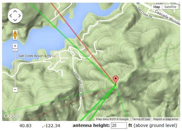
I then moved the teardrop cursor to the top of the hill south of you (20 ft up in the tree) and got this report:
http://www.tvfool.com/?option=com_wr...d2438e744b90c9
The signals look much better.
For your protection, I erased some of the coordinate numbers just the way tvfool does in a report that uses coordinates.
10 ft up:
http://www.tvfool.com/?option=com_wr...d243424a5cb5be
5 ft up (if nothing is in the way in front of it):
http://www.tvfool.com/?option=com_wr...d2432a53ca1d25
If you decide to use a preamp up the hill, use RG6 that has a solid copper center conductor rather than copper coated steel. The voltage loss for the preamp is much less with the solid copper conductor. The TV signals just use the copper coating, but the DC for the preamp uses the full cross section of the conductor. RG11 would have less loss, but it is a lot of trouble to work with.
Last edited by rabbit73; 25-Sep-2014 at 12:21 AM.
|
|
|
|
|
24-Sep-2014, 1:36 PM
|
#6
|
|
Junior Member
Join Date: Aug 2014
Posts: 18
|
Beautiful. I'm hoping that's the hill I'm working with. How would I mount my antennas in the tree? I was planning on just using rebar for a ground rod at he tree but do I need to ground anywhere else?
Last edited by docsuess84; 25-Sep-2014 at 4:57 PM.
|
|
|
|
|
24-Sep-2014, 3:39 PM
|
#7
|
|
Retired A/V Tech
Join Date: Aug 2012
Location: S.E. VA
Posts: 2,747
|
After grounding the mast at the top, the coax shield at the lower end should be grounded with a grounding block to your electrical system ground for electrical safety. If you use a messenger support cable for the coax, it probably should also be grounded.
Don't try to do the whole permanent setup at once. First try a temporary setup with just one antenna and no preamp on the hill to see what you will get. It will take some trial and error to get what you want.
Last edited by rabbit73; 27-Sep-2014 at 12:44 AM.
|
|
|
|
|
25-Sep-2014, 12:44 AM
|
#8
|
|
Junior Member
Join Date: Aug 2014
Posts: 18
|
So if I understand correctly, grounding block/rods at the base of the tree, where the coax enters the house, and messenger cable if I use it. I played with the coordinates, and it appears like I can get a similar decent signal at a different point on the hill at 10' that is closer to my house. I'm rethinking using conduit and going with direct bury since all the labor is on me, and I'm trying to reduce the amount of time I play in the forest to keep my wife from wanting to kill me. I have some more unanswered questions:
1. The guy at Lowes said a piece of rebar would work just fine as a ground rod. Is he an idiot?
2. Where/how is the best place to mount the antenna(s) on the tree? Trunk? Horizontal branch and using what hardware?
3. The instructions for the preamp state the indoor power supply cant be more than 150' away, yet mine will greatly exceed that. Is that ok, or is that why I'm going with the solid copper core?
4. If I want to split the signal 3 or 4 ways (2, possibly 3 tv's and FM tuner), will I need an additional drop amplifier at the end of a 300-400' coax run to distribute it effectively, or is the preamp by the antenna enough?
5. On the note of FM, I read that if I join two antennas together pointed in different directions, I should turn the FM switch off of the preamp to avoid reduced performance. How would I go about incorporating FM reception into my set-up in light of that?
Granted, I need to just set the dumb thing up and see what works and what doesn't, but I wanted to plan ahead. Thanks for your help everybody. Learning how to do all this is really fun.
|
|
|
|
|
25-Sep-2014, 12:48 AM
|
#9
|
|
Retired A/V Tech
Join Date: Aug 2012
Location: S.E. VA
Posts: 2,747
|
Quote:
|
So if I understand correctly, grounding block/rods at the base of the tree, where the coax enters the house, and messenger cable if I use it.
|
Probably no grounding block for the coax shield at the base of the tree, but grounding of the mast is a good idea at the hilltop because it is an elevated exposed area.
Some information on grounding on this forum:
General Technical & Safety Information
http://forum.tvfool.com/showthread.php?t=901
Grounding Question
http://forum.tvfool.com/showthread.php?t=14748
And since your antenna will be at the top of the hill, here is a good reference:
Amateur Radio Station Grounding and Lightning Protection
http://www.bwcelectronics.com/articles/WP30A190.pdf
Quote:
|
1. The guy at Lowes said a piece of rebar would work just fine as a ground rod. Is he an idiot?
|
It will work if the connection is good. Electricians use an 8 ft grounding rod to meet NEC specs; a 4 ft rod is too short.
Quote:
|
2. Where/how is the best place to mount the antenna(s) on the tree? Trunk? Horizontal branch and using what hardware?
|
If the branches are high, then on the trunk. You don't have to use a tree; you could use a metal mast. It is difficult for me to visualize your area at the top of the hill. You will need to use your own creativity.
Quote:
|
3. The instructions for the preamp state the indoor power supply cant be more than 150' away, yet mine will greatly exceed that. Is that ok, or is that why I'm going with the solid copper core?
|
The rule-of-thumb is that the solid copper core gives you twice the distance as copper coated steel. What it boils down to is this: is there enough voltage at the preamp for proper operation? Many of the new preamps use more current (300 mA, meaning more voltage drop) than the older preamps, like the original CM7777 (125 mA). My original CM7777 is very tolerant of reduced voltage. Pete Higgins has made some tests of his RCA preamps for current and voltage, attachment #4. He has a thread on this forum about it:
RCA TVPRAMP1R Amplifier
http://forum.tvfool.com/showthread.php?t=13530
To give you an accurate answer, I would need to make measurements at your location.
Quote:
|
4. If I want to split the signal 3 or 4 ways (2, possibly 3 tv's and FM tuner), will I need an additional drop amplifier at the end of a 300-400' coax run to distribute it effectively, or is the preamp by the antenna enough?
|
A drop amp will probably be needed, like the CM341x series. Try without a drop amp with just one TV. Do you have a TV that has a signal strength indicator to give you an idea of how weak the signal can be just before dropout? If the run is 300-400 ft, then you have now graduated to RG11 coax or even 75 ohm hardline that cable companies use for long runs. Calaveras (AA6G) of avsforum.com uses hardline for his long run; 480 ft of 1/2 inch hardline. See attachment #1.
Quote:
|
5. On the note of FM, I read that if I join two antennas together pointed in different directions, I should turn the FM switch off of the preamp to avoid reduced performance. How would I go about incorporating FM reception into my set-up in light of that?
|
That's not a good idea for your situation. Keep the FM separate for simplicity. However, Calaveras made it work as you can see in his diagram, but he is a lot smarter than I am. Attachment #2 is your FM signals down the hill; attachment #3 is your FM signals up the hill. KSHA, 104.3, is very strong.
Last edited by rabbit73; 27-Sep-2014 at 11:05 PM.
|
|
|
|
|
25-Sep-2014, 2:03 AM
|
#10
|
|
Junior Member
Join Date: Aug 2014
Posts: 18
|
After reading that grounding article I feel more confused. He makes it sound like ground wire should travel the length of the coax and terminate and then down to the house ground. While shopping for cable I saw RG6 that had ground wire with it. Should I do that or can I just run ground wire from the block to the house ground like I thought?
|
|
|
|
|
25-Sep-2014, 2:38 AM
|
#11
|
|
Retired A/V Tech
Join Date: Aug 2012
Location: S.E. VA
Posts: 2,747
|
My quick answer is run ground wire from the block to the house ground. This would allow you to use other types of coax that have lower loss for the signals and for the DC power for a preamp if needed.
The RG6 with an attached 17 gauge grounding wire is popular with the dish guys for a simple installation.
If you use RG6 without a preamp you are limited to your strongest signals. If you add your RCA preamp at the hilltop, there might not be enough voltage for proper operation with a long coax run. Pete Higgins has solved this problem by running extra wires for the preamp DC power and putting a voltage regulator and power injector near the antenna. This would be a custom solution rather than an off-the-shelf solution.
You can see what networks are available at your zip code here:
http://www.rabbitears.info/search.ph...pe=dBm&height=
Last edited by rabbit73; 27-Sep-2014 at 10:34 PM.
|
|
|
|
|
25-Sep-2014, 8:58 PM
|
#12
|
|
Junior Member
Join Date: Aug 2014
Posts: 18
|
Where are the best options for bulk/surplus cable? Googling is fairly overwhelming and half the time I can't tell the difference between the stuff. I stopped by my local cable office, and the help person said she could give out RG6, but couldn't do anything else. Electrical suppliers around here had no idea what I was talking about when I asked about 75ohm hardline, and they wanted over a dollar per foot for RG11.
|
|
|
|
|
26-Sep-2014, 11:21 PM
|
#13
|
|
Retired A/V Tech
Join Date: Aug 2012
Location: S.E. VA
Posts: 2,747
|
Please don't buy any coax yet based on my quick answer in post #11. I need to review the NEC and get back to you.
Quote:
|
After reading that grounding article I feel more confused.
|
A lot of people, including myself, are confused by the requirements of the NEC. You can see the controversy that surrounds it in the grounding threads. The NEC was written for electrical professionals, and was never meant for the layman. And, to make it even more confusing, there are often many changes to the NEC.
Here is another grounding thread:
Grounding Antenna and Dish
http://www.avsforum.com/forum/25-hdt...enna-dish.html
Last edited by rabbit73; 27-Sep-2014 at 1:07 AM.
|
|
|
|
|
27-Sep-2014, 6:39 AM
|
#14
|
|
Retired A/V Tech
Join Date: Aug 2012
Location: S.E. VA
Posts: 2,747
|
I reviewed the NEC antenna grounding rules. It requires two grounding connections for an outdoor antenna. The mast must be connected to the house electrical system ground with a 10 gauge copper, 8 gauge aluminum, or 17 gauge copper coated steel conductor. The coax shield must be grounded using a grounding block that is also connected to the house electrical system ground. The NEC calls the grounding block an ADU (antenna discharge unit). The purpose of the grounding is not to withstand a lightning strike, but to prevent a buildup of a static charge on the antenna system which, in theory, reduces the chance of a strike, and for electrical safety. You can see a diagram of this on page 2 in the AntennasDirect link that GroundUrMast gave you in his General Technical & Safety Information thread:
https://www.antennasdirect.com/cmss_...structions.pdf
If you use a separate ground rod for an antenna mast ground, then that ground rod must be connected (bonded) to the house electrical system ground with a 6 gauge copper wire. This is to prevent a voltage differential between the two grounds.
You can see a diagram of the separate ground rod version in the link that GroundUrMast gave you:
Antenna basics
http://www.hdtvprimer.com/ANTENNAS/basics.html
scroll down to The NEC requirement
In your case, the antenna mast is at the top of the hill. This would mean, for a strict interpretation of the NEC, a very long 6 gauge wire, which doesn't seem very practical. These days, copper is not cheap. A reel of 300 ft of 6 gauge bare copper grounding wire (solid or stranded) will cost you $200 to $300. Dish installers have a similar problem, which is why they often use coax with an attached 17 gauge copper coated wire to ground the dish structure and ignore the 6 gauge bonding wire requirement.
http://www.dbsinstall.com/diy/Grounding-2.asp
If you plan on doing the grounding work youself, be sure not to disconnect the grounding connection for the house ground even for a second when adding your grounding wires, and also the dish wires. Use split bolts that allow you to add your wires to the house ground. There is a device mentioned by GroundURMast called an Intersystem Bonding Termination that allows you to connect your grounds without disturbing the house ground because it has a lay-in connection for the house ground conductor. I saw it being used on a recent This Old House show:
http://www.erico.com/public/library/fep/LT1476.pdf
I find your intelligent questions about your installation almost over my head. I have a fairly good grasp of the theory, but I don't have much practical experience with an installation like yours that requires some custom solutions for your problems:
I don't know about the regulations in your area for an antenna installation. Some towns require an electrical inspector to give an OK for an installation; others don't seem to care. I would hesitate about asking your inspector about your installation until you find out what kind of person he is. Ask a local electrician about the inspector when he helps you with your ground connections to your electrical system. The dish guy would also know about your inspector and if any inspections are required. There is a device called an OTA/satellite diplexer that allows the same coax to be used for both signals. It usually allows DC power for the dish to get thru, but I don't think it will power your preamp.
http://www.hollandelectronics.com/ca...-Diplexers.pdf
A long run of RG6 coax has a signal attenuation of about 6 dB per 100 ft for UHF. RG11 is only a little better at 5 dB, and 1/2" 75 ohm hardline about 2.5 dB. The question is whether the reduced attenuation of the larger coax is worth the expense. The other consideration is how much the coax will reduce the voltage to the preamp, if you use one. Pete's chart for the RCA preamp shows the output voltage of the regulator, but it doesn't tell us how much the voltage can be reduced and still allow proper operation. In his earlier installation he used a separate voltage feed wire to the top of his tower and added a voltage regulator near the preamp. Calaveras used a custom power supply for his power injector that delivered enough voltage to his preamp on the upper end of his long coax.
Before you spend a lot of money, I suggest that you consult a senior level guru like Pete Higgins or Calaveras (they live in California) about your installation. Both of them have towers, long runs of coax, and have integrated FM into their antenna systems. You can see how they have solved their problems in the diagrams in the attachments. You can send them a PM; Pete Higgins often comes to this forum, and Calaveras is often found here:
The Official AVS Antenna and Related Hardware Topic
http://www.avsforum.com/forum/25-hdt...are-topic.html
Last edited by rabbit73; 27-Sep-2014 at 10:05 PM.
|
|
|
|
|
1-Oct-2014, 12:24 AM
|
#15
|
|
Retired A/V Tech
Join Date: Aug 2012
Location: S.E. VA
Posts: 2,747
|
I tried some tvfool reports using the coordinates for your new hill location. The signals are not as good as the first hill location in post #5 at 10 ft, but still usable:

10 ft:
http://www.tvfool.com/?option=com_wr...d2438143458058
CH7 NM 42.3 dB 1Edge
CH9 NM 36.2 dB 1Edge
CH38.1 NM -29.3 1Edge NG
20 ft:
http://www.tvfool.com/?option=com_wr...d243a64bf5b603
CH7 NM 47.6 dB LOS
CH9 NM 43.3 dB LOS
CH38.1 NM -11.8 1Edge maybe with preamp and separate UHF antenna
30 ft:
http://www.tvfool.com/?option=com_wr...d243f318247686
CH7 NM 50.1 dB LOS
CH9 NM 45.4 dB LOS
CH38.1 NM +19.2 dB LOS looking better but still with preamp and separate UHF antenna
10 ft would probably give you 7 and 9, but not 38.
At 20 ft 7 and 9 are looking good; 38 might be possible with a separate high gain UHF antenna.
At 30 ft all are LOS and looking excellent.
If you can get your antenna high enough at the new hill site you have a good chance for at least 7 and 9 without a preamp. One factor in your favor is that the coax loss for VHF-high is much less than for UHF; about 2 dB per 100 ft VS 6 dB per 100 ft of RG6.
400 ft of RG 6 would give a loss of 8 dB which you would subtract from the NM figures for 7 and 9.
Antenna gain can be added to the NM figure and the signal pwr figure. You can add the preamp gain to the signal pwr figure, but you can't add the preamp gain to the NM figure without subtracting the preamp NF because the preamp NF reduces the SNR of the signal.

Andy S. Lee, the creator of this forum, has a good post about NM here:
http://www.avsforum.com/forum/25-hdt...l#post15700679
You can make Andy's diagrams larger by clicking on the 2nd set at the end of his post. They were attachments before AVS switched to a new (UGH!) software and added so many ads that they squeezed the posts to a narrow width, giving the impression that ads are more important than the posts. Click again on each diagram if you see a plus sign on your cursor, which will make the diagrams even larger.
Last edited by rabbit73; 1-Oct-2014 at 2:18 AM.
|
|
|
|
|
3-Oct-2014, 1:56 AM
|
#16
|
|
Retired A/V Tech
Join Date: Aug 2012
Location: S.E. VA
Posts: 2,747
|
Quote:
|
I'm rethinking using conduit and going with direct bury
|
What did you decide about how you will run your coax up the hill?
What TVs are you using; do they have digital tuners, or are they analog TVs with converter boxes?
Do you have a TV that has a signal strength indicator? It would be helpful to be able to tell how strong your signals need to be for reliable reception.
Quote:
|
How would I mount my antennas in the tree?
|
I thought a little more about that question. If you mount your antenna on a tree you will need to fasten a horizontal support to the tree that sticks out from the trunk with a vertical section of metal mast at the end of that support. Most antennas have a clamp that fastens to tubing that is 1-1/4 inch in diameter. The mast should be grounded with a heavy gauge copper wire to an 8 ft copper coated steel ground rod driven into the ground at the base of the tree. Use this type of clamp to connect the wire to the rod:

The wire goes between the rod and the V notch, not under the end of the screw.
The coax should be grounded down at the house to a grounding block to drain any static buildup. Since the coax will be connected to AC operated equipment in the house, grounding the coax will also protect you from shock if any of the equipment becomes defective and from normal leakage current that exists on all AC operated equipment.
http://www.digitalhome.ca/forum/show...postcount=1099
http://www.digitalhome.ca/forum/show...postcount=1022
http://www.digitalhome.ca/forum/show...postcount=1025
If there is a nearby strike at the antenna the current created by the EMP will favor (we hope) the low resistance path to the ground rod instead of going down the coax to the house. If there is a direct strike, there isn't much you can do, your installation will be toast.
An alternative support for the antenna would be a metal mast inserted into the ground. A 10 ft mast is expensive to ship, so you can pick one up from a local store like the Radio Shack in Reading:
http://www.radioshack.com/product/in...ductId=3739599
The self-supporting metal mast should be grounded to a grounding rod as described above.
Home Depot sells a fence top rail that is galvanized 17 gauge that is a little less expensive:
http://www.homedepot.com/p/YARDGARD-...3DPT/100322532
If you want to go higher than 10 ft, you can add more sections, but it will no longer be self-supporting and will need guy rings and guy wires. You can also buy a push-up mast.
http://www.cableandwireshop.com/telescoping_masts.html
http://www.texastowers.com/towers/pushup.htm
Last edited by rabbit73; 6-Oct-2014 at 2:06 AM.
|
|
|
|
|
3-Oct-2014, 4:32 AM
|
#17
|
|
Junior Member
Join Date: Aug 2014
Posts: 18
|
I examined the sattellite installer's handiwork because I was curious what he ended up doing. I didn't go up to the dish itself but I followed his coax run, and he had it going to a grounding block on one of my backyard fence posts and then grounding wire running approximately one foot to a grounding strap on my well pump. As I mentioned, my house has no central ground. All electrical implements that I can see have been grounded to pipes attached to our well near the pump house. Since they are all connected via cold water pipes, did his method satisfy the bonding requirement? I did not see a seperate wire so I'm assuming he did not utilize a rod up by the dish itself. Can the coax accomplish the joint task of carrying signal as well as grounding the mast?
|
|
|
|
|
3-Oct-2014, 6:11 AM
|
#18
|
|
Retired A/V Tech
Join Date: Aug 2012
Location: S.E. VA
Posts: 2,747
|
Quote:
|
I did not see a seperate wire so I'm assuming he did not utilize a rod up by the dish itself
|
If you did not see a separate wire, I'm assuming he did utilize a rod up by the dish so that the coax would not have to carry the high current induced by a nearby strike.
If the dish mount is in contact with rebar or wire mesh in the concrete, that can serve as a ground.
I was under the impression that a dish for internet service uses multi-conductor coax to carry upstream and downstream data plus power and grounding wires.
http://www.dbsinstall.com/diy/Grounding-5.asp
How's that for a very complicated description?
You will just have to look up there and see what he did. It's hard for me to imagine that he didn't provide a ground for the dish at either end of the coax. If that is the Hughes way because they feel that their lower resistance coax can do both grounding jobs---OK, but I'm not convinced it's the best way for you.
At least he did ground the coax down by the house.
Is there any way you can ask him?
As you previously said to me:
Quote:
|
Why string a long strand of copper and bring electricity closer to my home as opposed to discharging it into the hillside on a seperate rod?
|
Didn't you?
I thought you had decided on the best way for your installation. A long strand of copper is no more likely to bring electricity closer to your home than the shield on your coax. That's why the NEC requires BOTH to be grounded your house electrical system ground.
Quote:
|
Can the coax accomplish the joint task of carrying signal as well as grounding the mast?
|
Maybe that's the Hughes way, but I'm not convinced that's a good idea for you, unless the coax has an attached 17 gauge copper coated steel grounding wire.
But, then, I'm not a Hughes, grounding, or NEC expert.
I've told you everything I know about grounding, and am tired of talking about it. It's your responsibility, not mine, to decide how your antenna installation should be grounded.
Your antenna project is not a simple one. If you are having trouble deciding how to do it, maybe you should hire someone to do it for you.
Whenever I'm faced with a complex project, I try one of the easy options first. This keeps me from being paralyzed by indecision. The results of that test usually tells me what to try next, which gives me the confidence to continue.
You already have an antenna, some coax, and a location on the hill.
I think it's time for you to see what kind of signals you can get down to your house by setting up a temporary test, before the FCC auctions off any more TV channels.
Last edited by rabbit73; 12-Oct-2014 at 2:00 AM.
|
|
|
|
 Posting Rules
|
You may not post new threads
You may not post replies
You may not post attachments
You may not edit your posts
HTML code is Off
|
|
|
|
|


