Quote:
|
For instance, my dad's old VHF/UHF was clearly two different antennas sharing a common structure, one in front of the other. There was only one wire coming out of it, so they had to combine them somehow.
|
There are two ways now being used to combine the UHF and VHF sections of the "one-in-front-of-the-other" combo antennas.
The Winegard combo antennas like the HD7694, 97, and 98 use a circuit board combiner Winegard VHF/UHF Terminal Board Housing for CA/HD Antennas (CB-8269) in a small housing that functions like a UVSJ.
http://www.amazon.com/Winegard-CB-82.../dp/B003H2G5ZM
http://www.solidsignal.com/pview.asp?p=cb-8269
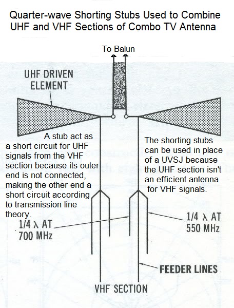
Most other combo antennas use two sets of quarter wave stubs on the open wire feedline between the VHF and UHF section. The stubs short out the UHF signals that might be picked up by the VHF section, and the balun connects to the UHF driven element. There are two sets of stubs, each a slightly different length to cover the UHF band.
The quarter wave stubs stick out from the lines with their outer ends not connected. This becomes a high impedance point. According to transmission line theory, the other end connected to the line becomes a very low impedance point which shorts out the UHF signals on that line before they arrive at the combining point at the UHF driven element where the VHF and UHF signals are combined.