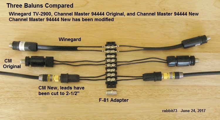
When I was making the measurements of the New CM balun, I noticed the loss readings would vary according to the position of the 300 ohm wires between them. I decided to cut the wires to 2-1/2" before removing the insulation to see of it would make any difference.
I then made measurements of this modified balun:
Code:
Channel Master New 94444 Balun with 2-1/2" Wires

Ch        F-81  Bal  Dif  Ea
          ---dBmV--  --dB---

15        7.3   4.8  2.5  1.3

28        6.4   4.7  1.7  0.9

45        5.6   3.8  1.8  0.9
The loss was reduced and was much less affected by the position of the wires. The long wires formed a transmission line of indefinite impedance.
If you use the new CM balun, I suggest you keep the wires short.
If you need a low loss balun for weak signal reception, I suggest a halfwave coaxial balun.
The PCB baluns in the new UHF antennas have low loss, but they are good for only one band. If you need a balun for UHF and VHF, use a conventional ferrite core balun like one of the above.