 9-Apr-2020, 12:57 AM
|
#3
|
|
Antenna Enthusiast
Join Date: Mar 2016
Location: Beach Park IL
Posts: 318
|
Build details...
Tripelo, thank you for your Insight. You asked me about the bending strength of the inch and a half aluminized exhaust tubing that forms the crossbar between the two booms. Tubing is fairly stout.
I didn't notice it till I mocked up the antennas in my shop and saw one of the uprights wasn't exactly parallel / level. When I brought the tubing back, I thought he would want put it back in the machine but he said no we can tweak it by hand. It takes a machine to bend it, but you can tweak it with your full body weight (215 lbs) a few degrees. Which is in fact, how we got the bend perfect.
I decided to go with the drill holes already available on the forward section from the donor 30 - 2476. It seemed that the pattern was 10 1/2" anyhow towards the front. So what I did was rearrange the front sections directors taking the wider ones from the donor section and adding them to the existing antenna and vice versa with the smaller ones from the base antenna and moving them to the donor section that forms the extension.
This created a not so easy to solve problem when joining the donor section to the existing antenna. The director spacing would have been too close so I went to my local hardware store to see if I could find some square box tubing to sleeve the inside of the two antennas and thereby creating an extension. I definitely could not have used the clamp that goes between the two sections because of the 4" gap.
In this way I was able to keep a 10 and a half inch spacing on the front directors. Not knowing what else to do, I figured that's all I can do. There was a lot of drilling to do after installing these reinforcements so I could reattach the directors. That was fairly easy to do and I have my son do it to learn how to operate a drill. And of course aluminum drills quite easily.


However, that size box tube for sleeving was not available but I did find some "C" channel that was exactly the right size to slide inside. Not what I wanted but it would have to do. I later found some "C" channel that fit the outside also. So I decided to go the length of these 8 foot sections inside the Boom length and braced it from underneath using the larger 8 foot U channel. The photo here shows the "C" channel but doesn't give a good idea of how it was used. I'll supply an end-on picture later....

This was the only solution I could come up with on a short notice. I would say that it is still somewhat saggy. I also decided to leave the excess of the "under brace" hanging past the extension boom simply because I don't know if I want to add another section and I don't think it will hurt anything.

The following photos show the amount of sag in the booms, possibly affecting the reception by not allowing the directors to stay on the same plane:
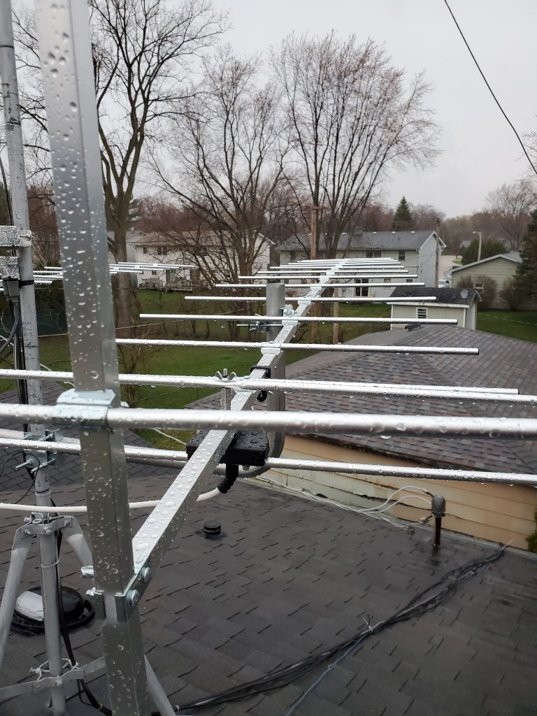

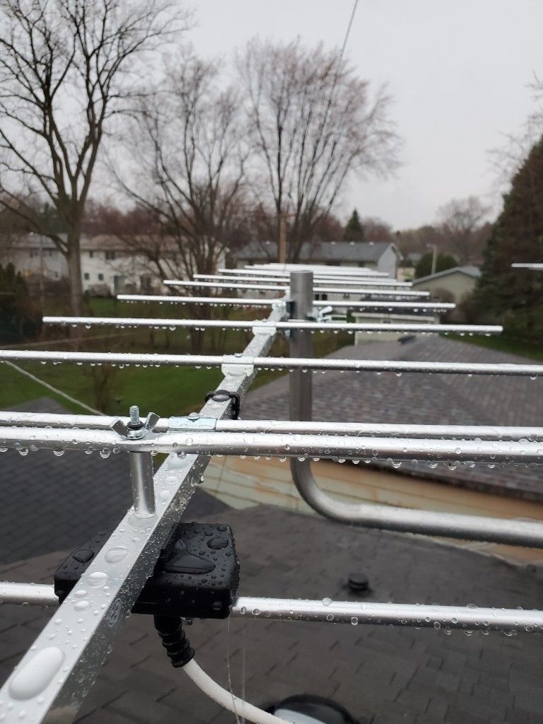
I may need to put a support wire at the end of the boom up to some sort of upright to pull the end of the boom up to take the sag out of it.
Last edited by bobsgarage; 23-Oct-2020 at 8:30 PM.
|

|

|