Quote:
Originally Posted by tripelo

Would like your thoughts on dynamic range of Airspy vs. SDRplay RSP1.
Thanks
|
I did some additional tests with the SDRplay RSP1A and the RSP Spectrum Analyser (British spelling) software.
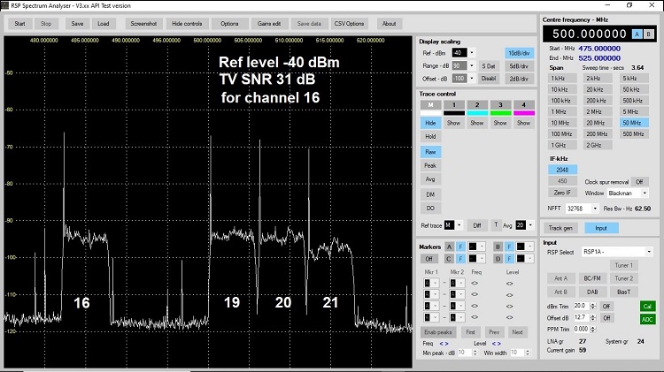
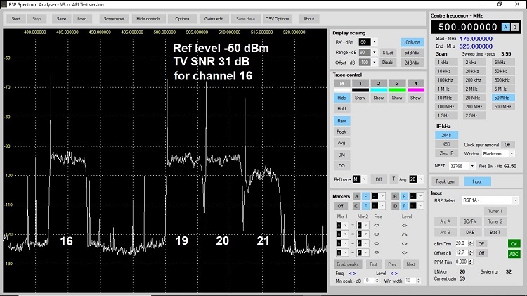
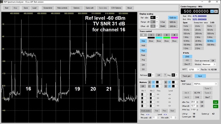
It seems that it is necessary to properly set the Reference level of the RSP Spectrum Analyser. If you set it too high, part or all of the signal will be buried in the noise.
The RSP Spectrum Analyser tries to simulate what a real spectrum analyzer does. You have to be careful with the Display scaling settings to get a correct representation of SNR. Manual:
https://www.sdrplay.com/docs/RSP-Spe...lyser-V1.1.pdf
Setting RSP Spectrum Analyser Reference Level
Quote:
Reference Level
A common error is a complaint that signals with a 40-50 dB SNR as displayed on SDRuno, shows a signal barely breaking through the noise floor on the analyser. In almost all cases, AGC is enabled on SDRuno, and the LNA gain reduction slider set at a low gain reduction value resulting in a lower noise floor. IF gain reduction will be whatever the AGC system sets it at.
Conversely, the analyser is usually set at a high reference level of somewhere between -30 to+10 dBm, has a very high noise floor and sees little or no signal above the noise. This is usually caused by the user attempting to use the reference level control to position the trace within the display area, instead of using the range and offset controls provided for this purpose.
The reference level should initially be set to around -80 dBm, while ensuring the ADC is not overloaded and spurious signals are not generated. This will give maximum sensitivity and a lower noise floor. Increasing the reference level towards 0 dBm will result in an increasing noise floor, and depending on signal level, may result a lower S/N ratio. Use the range and offset controls to scale and position the display as required.
|
An example:

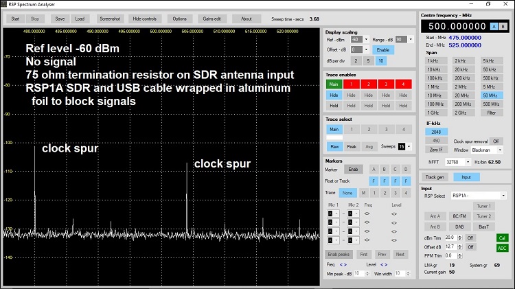
Testing for spurs:
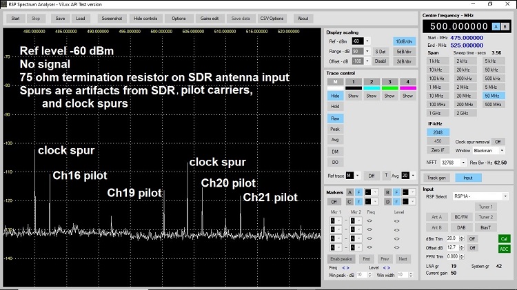
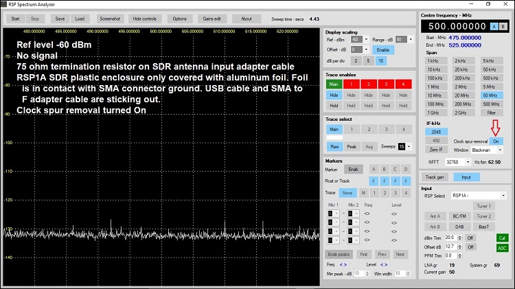
Then I decided to just wrap the plastic SDR enclosure in foil and turn On the Clock spur removal
CONCLUSIONS:
It is important to properly set the Reference level to display the correct SNR.
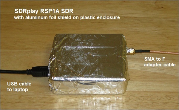
The RSP1A has a plastic enclosure that is letting strong signals through. I had hoped that the inside of the plastic enclosure had been sprayed with a conductive paint that would act like a shield, but apparently that wasn't done.

The aluminum foil that I put on the outside of the enclosure, and contacting the ground of the SMA antenna input connector, acted as a substitute shield.
The RSP2 looks like it has a conductive coating inside:
