Referring to hybrid combiner
in earlier post:
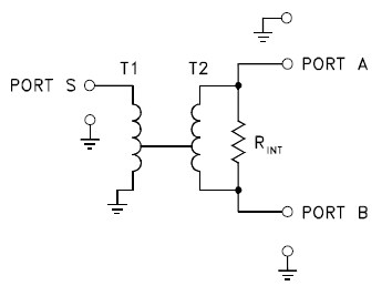
A hybrid splitter/combiner schematic may look something like this schematic from Mini-Circuits.
- Ports A & B are splitter outputs or combiner inputs.
- Port S is the combined port.
It seems that most common splitters available are not configured as above. To find a splitter with good isolation between ports, it's probably best to look for a splitter with specified isolation. An isolation value between input ports of 30 dB is good number.
Attempting to add clarification to Case 3 in the previous post. Both the TV signals and the noise, being independent, suffer ~3 dB attenuation from one input port to output, or combined port, of the hybrid combiner. This ~3dB loss results from internal circuitry to provide isolation. There are also additional normal circuit losses that ranges from tenths of a dB to a few dB.
Noise power from two independent sources above the noise floor (kTB) is additive in a hybrid combiner. Equal noise power above noise floor at each input adds at output. So relative to signal power, the noise experiences no loss (3 dB loss through single port, plus 3 dB combined gain). The signal has no combined gain since the other input port does not contain that particular signal.
About Noise floor & kTB:
Because of the preamplifier’s gain, the noise power at combiner inputs is above the noise floor.
KTB, thermal background noise is a major contributor to the noise floor at UHF and above. Man-made and galactic noise can contribute to the overall noise floor but mostly these affect VHF more than UHF.
The overall result is that S/N is reduced 3 dB (hence the twice the noise mentioned in the previous post). Different signal frequencies from the separate antennas pointed in different directions do not coherently add in the combiner. Combiner circuit losses affect both the signal and the noise so this is where the gain of the preamplifier in front of the combiner can help with improved signal to noise ratio.
Assuming all three cases utilize identical preamplifiers, with preamplifiers after combiner in Case 1 & 2, then:
In general compared to single antenna, single preamp, and no combiner, all 3 cases lose S/N at combiner output (by about 3 dB plus).
Case 3 differs:
- Mitigates 2nd antenna loading losses (Case 2) and
- Via gain of preamplifiers, overcomes the additional normal circuit losses in the combiner (Case 1). Although they exist, no transmission line losses are assumed in Case 2.
- The noise figure of two preamps must low enough, so as to be a small contributor to final S/N, else Case 3 could make situation worse.
As the
example in the previous post, All cases have interesting specific applications in which they may have some advantage.
-------------------
Will make a small edit to Case 3 in earlier post to help with clarification.