View Single Post
Old 11-Apr-2016, 6:15 PM   #27
rabbit73
Retired A/V Tech
 
Join Date: Aug 2012
Location: S.E. VA
Posts: 2,747
Quote:
I added a picture (wish I could show the picture or a thumbnail.
I can display it for you; nice job, chris.


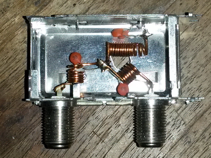
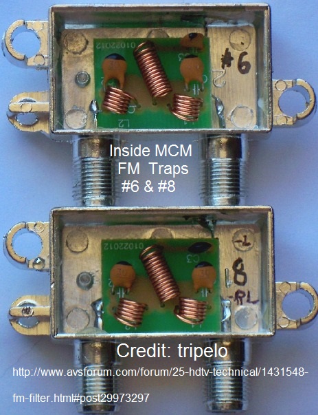
This is what the MCM FM Trap looks like inside:


diagram


Quote:
Do you happen to know what is inside an HLSJ?
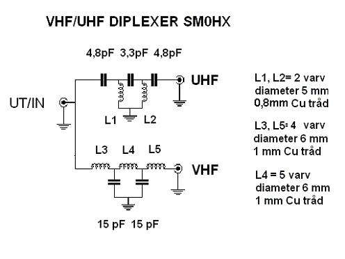
Inside is a low pass filter and a high pass filter, just as there is inside a UVSJ, but for different frequencies. The general term for these filters is a diplexer. All UVSJs are diplexers, but not all diplexers are UVSJs.

Here is a DIY 5-pole Diplexer, AKA UVSJ:


DIY photos
http://www.is0grb.it/duplexer/

DIY 3-pole HLSJ; 5-pole would be better:
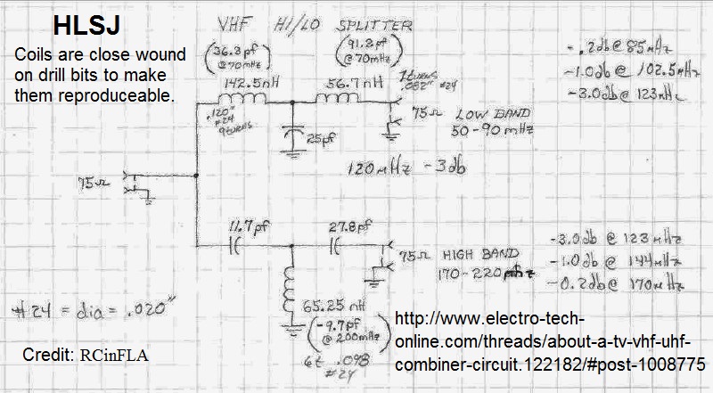


source:
http://www.electro-tech-online.com/t...ircuit.122182/
post #12
http://www.electro-tech-online.com/t.../#post-1008775
Attached Images
File Type: jpg chris1379TVFdiyFMfilter2.jpg (225.9 KB, 3894 views)
File Type: jpg Inside%20MCM%20FM%20Trap%20#6%20&%20#8.jpg (115.7 KB, 3188 views)
File Type: jpg MCM FM Trap Sim.JPG (111.4 KB, 4197 views)
File Type: jpg VHF-UHF Diplexer SM0HX.jpg (22.8 KB, 5494 views)
File Type: jpg VHF Hi-Low Splitter Diag_1.jpg (142.7 KB, 3630 views)
__________________
If you can not measure it, you can not improve it.
Lord Kelvin, 1883
http://www.megalithia.com/elect/aeri...ttpoorman.html

Last edited by rabbit73; 12-Apr-2016 at 11:32 AM.
rabbit73 is offline   Reply With Quote