Part 4 (continued from previous post)
4NEC2 Analysis and Discussion
Antenna simulation software (4NEC2) could be useful in comparing antennas. Generally, software analysis is not a substitute for field tests. Choices must be made of available approximations that are necessarily incorporated in software models. Without some field measurement data to guide the design of a simulation model, rarely does a simulation model account for all factors in an antenna design.
In cases where field data is limited, but available enough to help confirm the models and if one can be fairly sure the software model something close to reality, then software analysis can provide insight.
The physical dimensions of both antennas; the ClearStream 5 and the Televes Yagi B-III were measured and software models created in 4NEC2.
The gain values shown in the following 4NEC2 results do not include balun loss or mismatch loss.
Below are images of the results of 4NEC2 analysis
Top Image, Gain in dBi, Lower image SWR
(Recall dBi=dBd+2.15)

The above simulation SWR results agree favorably with the actual measurements.
If the Antennas Direct ClearStream 5 gain were to be measured, likely it would also agree.
Below is an image that shows the Televes Yagi B-III antenna gain and SWR:
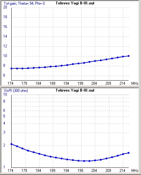
The shape of the Televes SWR pattern above above is in reasonable agreement with actual measurements (see previous post). Overall, the SWR is lower than measured. No explanation has been found. It could be that the software model does not account for some factor that could alter the SWR values. Another possibility is that the balun (not modeled) could contribute to the SWR difference. For example; In some cases LC components are added to a balun to improve response at band edges at the expense of impedance match at center band.
The above image illustrates the tendency of increasing gain for higher frequencies, often seen in Yagi-type antennas.
These simulation results are also in fair agreement with data present at the two manufacturers websites:
Antennas Direct ClearStream 5
Gain and SWR (simulations of both, plus measured values of SWR at 10 ft AGL),
Located in this document:
https://www.antennasdirect.com/cmss_...with%20uhf.pdf
Televes Yagi B-III (Gain),
Located in this document:
https://www.televes.com/sites/defaul...ennas_en_0.pdf
Azimuth Beam Width
The following images show the computed azimuth (horizontal) antenna patterns of the two antennas at three frequencies representing lower end of the band (174 MHz), mid band (194 MHz), and upper end of the band (216 MHz).

Note the C5 has a somewhat broader beamwidth, especially evident at the upper end of the band, than the Televes antenna.


The difference in gain at 216MHz is mainly related to increasing gain from the Televes B-III. The Televes B-III is advertised to cover up to 230MHz, so it is expected the gain would be higher at the upper end of the band.
(To be continued)
.