Returning to
VHF antenna tests, recall that an objective was to receive WBNA-8 and WHAS-11 from Louisville KY at distances of 70 and 101 miles. A project was initiated to determine if an antenna arrangement could make such reception possible.
TVfool report (both stations listed as 2-Edge):
Code:
		Noise Margin	Distance (miles)

WBNA-8           -7.2 dB	79.3
WHAS-11		-14.9 dB	101.1
A few antennas were compared at the test mast location (garage); Jerrold/Wade VIP-306, Channel Master Crossfire CM-3610, stacked pair of Winegard YA-1713, and a channel-cut Wade antenna.
Other high gain antennas were available, but only single units. It became fairly clear that no single antenna would suffice.
WHAS was listed as 2-edge and at the test site the signal was almost continuously variable. The actual signal strength, on an analog meter, fluctuated ~15 dB within something like 30 to 45 seconds. Portions of the WHAS 6 MHz spectrum varied independently.
The signal variation was such that antenna gain differences of maybe 1 or 2 dB were not visible.
It became apparent that, at this location, there were no commercial VHF signals strong enough or stable enough for definitive signal evaluation. Actually, there were no closer or stronger VHF signals at all. A local signal source was needed.
At the time in 2010, the signal
synthesizer discussed in earlier post had not been constructed. So, a 20 MHz crystal oscillator was built to use as a VHF transmitter. The 9th and 10th harmonic of the crystal frequency provided test signals for channel 8 (180-186 MHz) and Channel 11 (198-204 MHz). The signals from the crystal oscillator were fed to a transmitting antenna at the main tower.
The transmitting antenna was a portion of a YA-1713 mounted on reverse side of CM-4251 on the main tower. It was fed by coax from the crystal oscillator located on the ground. The transmit antenna was aimed toward the test mast (at the garage). The signal was then received by the antenna-under-test mounted at the test mast location. Height of receiving test antenna was adjusted to be ~ level with the transmit antenna (~45 ft. AGL).
The above arrangement provided stable signals for use in gain comparisons between candidate VHF antennas.
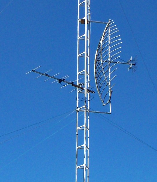
The image below shows the upper-VHF transmit test antenna.
Later, a crystal oscillator was built that could have provided UHF signals, but it was determined that a synthesizer was a better solution.
The crystal oscillator was used as a reference transmitter in tests throughout 2010, until the synthesizer was constructed in early 2011.
.